c. Block Diagrams.
Of all the diagrams used in electronics, the block
diagram is probably the simplest to understand.
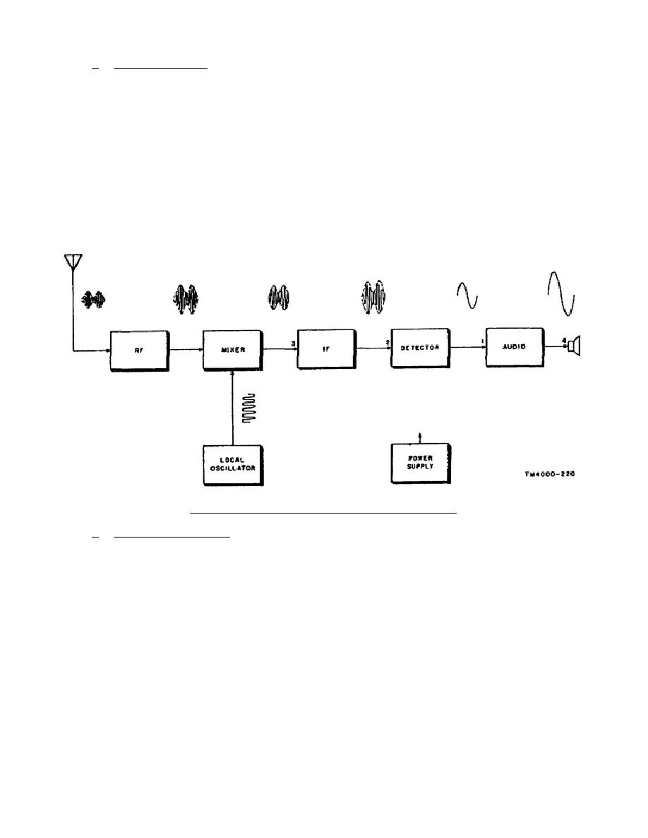
Figure 4-3 shows that the block
diagram is a series of "boxes," each representing a stage, or stages, in a radio
receiver.
An example of a multiple-stage block is the IF, which may include
several amplifier circuits.
As in this figure, waveforms are often included as
part of the block diagram.
Some block diagrams even show numbered test points.
The box is labeled with the function performed by the stage, the lines between the
boxes show the connections between stages, and the arrows indicate the direction of
signal flow. The block diagram presents the general idea of what is happening in
the unit, and is often used by the technician to localize trouble to a stage. A
block diagram can also be used to show an entire electronic installation. In this
case, each block represents a unit in the equipment, such as a transmitter,
receiver, power supply, etc. The block diagram would then be used to sectionalize
a trouble (determine which unit is defective). Since each of these units contains
many stages, there may be separate block diagrams representing each unit.
Figure 4-3.
Radio receiver block diagram.
d. Schematic Diagrams.
A schematic diagram can be compared with a roadmap.
A map uses symbols to show the highways, interconnecting roads, cities and towns,
structures, rivers and lakes, and other landmarks. A schematic is a diagram that
uses symbols to represent the tubes, transistors, resistors, capacitors, coils,
relays, and other components.
Some of the symbols that are commonly used in
schematics are shown in figure 4-4. The schematic shows how these components are
connected to make up the various circuits, and how these circuits are connected
into stages.
Each component is numbered, and its nominal value is either shown
with the component or listed in a table on the schematic.
(1) If the schematic is of a unit, such as a receiver, the stages of the
unit are usually labeled according to their functions (mixer,
oscillator, IF amplifier, etc).
Although the schematic is often all
the technician needs to locate a trouble in the equipment, it is more
often used in conduction with voltage, resistance, and, when
appropriate,
the
troubleshooting
chart to
isolate
a
defective
component.
309 L4
61


 Previous Page
