through the nonlinear portion of the low-current end of the curve, the local
oscillator frequency will mix with the incoming RF signal producing four
frequencies that will appear in the collector current: the local oscillator
frequency, the received signal frequency, the sum of the two, and the difference
between the two.
As with any other type of receiver, efficient mixing requires
that the local oscillator signal voltage be stronger than the incoming signal
voltage.
d. Output Circuit.
The collector current varies at the rate of both the RF
signal and the local oscillator frequencies.
Modulation (mixing) occurs as a
result of nonlinear operation, and the difference frequency from the mixing action
becomes the intermediate frequency.
Transformer T1 is tuned to select the
intermediate frequency, and all other modulation components (frequencies) are
ignored by the tuned circuit. A double-tuned transformer is used so as to obtain a
broad intermediate-frequency (IF) response and, at the same time, to realize a
resonant rise of voltage in the secondary. A tap on the secondary winding provides
a low-impedance output for the next stage.
Resistor R4 and capacitor C3 form a
filter network to rid the collector current of undesired frequencies.
2-4.
LOCAL OSCILLATOR
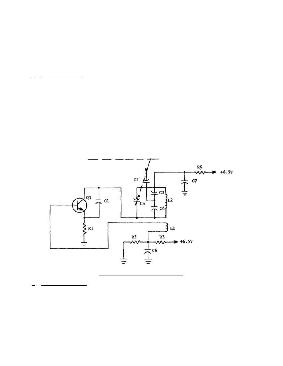
The oscillator stage, also
employing
a common-emitter circuit, is
shown in
figure 2-4.
Figure 2-4.
Local oscillator.
a. Feedback Circuit. The circuit is connected in a tuned-collector arrangement
that uses an untuned base coil L1 to provide the inductive feedback necessary to
sustain oscillations. Capacitor C5 tunes coil L2 to the
322 L2
10


 Previous Page
