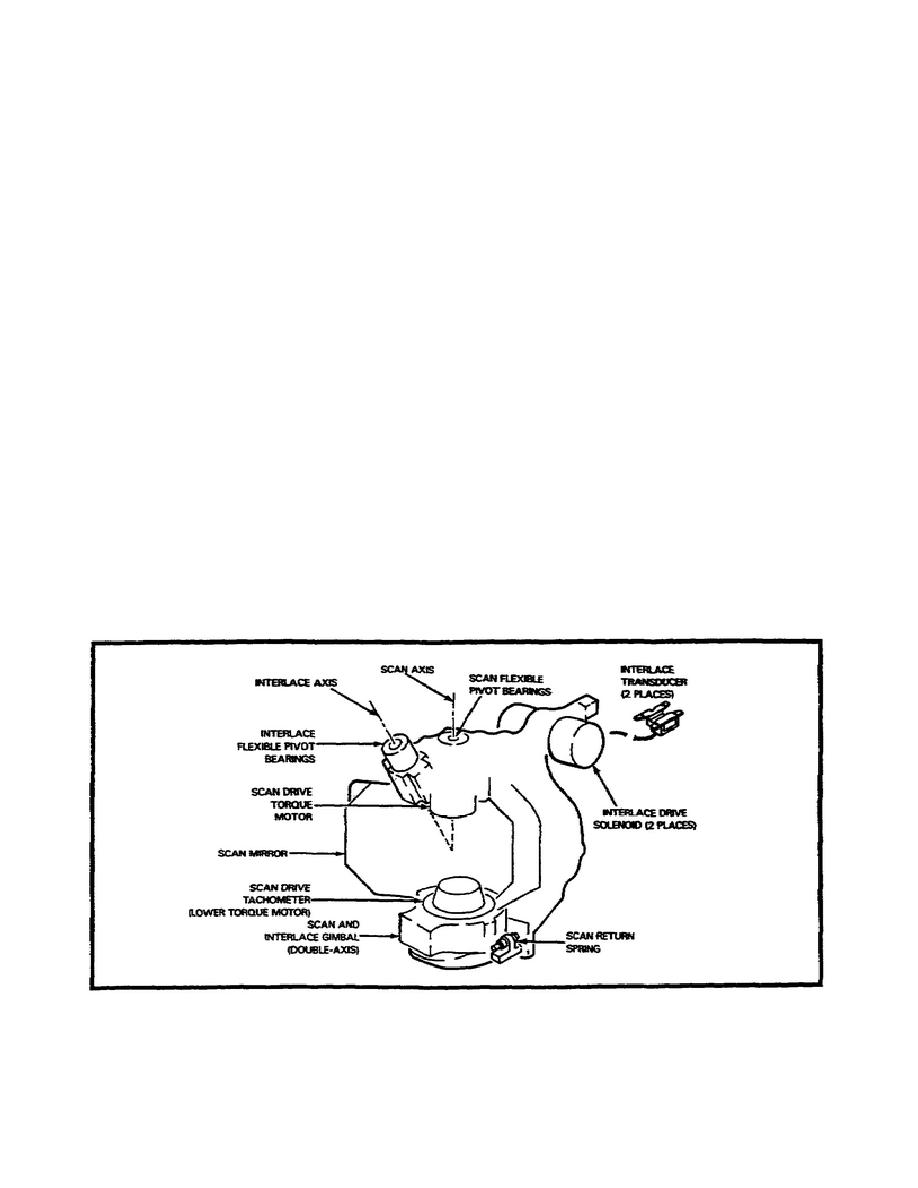
Mechanical Scanner.
The mechanical scanner (Figure 2-13) contains the scan and interlace
gimbal (double axis), scan drive tachometer, scan mirror, scan drive
torque motor, interlace flexible pivot bearings, interlace transducer
(2 places), interlace drive solenoid (2 places), and scan return
spring.
The scan mirror oscillates about the scan axis and interlace axis.
These motions are combined so the IR image is moved in a continuous
parallelogram shaped path over detectors to create the 2:1 interlace
pattern.
The front side of the scan mirror is coated for peak reflectivity in
the IR band and directs the incoming IR energy through the imaging
optics onto the array of IR detectors. The back of the scan mirror
is coated for peak reflectivity in the red LED array visual band, and
directs the LED array output through a set of collimating optics into
a visible display. The scan mirror is rotated about the scan axis by
the scan drive torque motor.
The lower torque motor is used as a
scan drive tachometer to provide scan velocity information to the
drive electronics.
Two interlace drive solenoids pivot the gimbal
assembly about the interlace axis during the time the scan return
arms are in contact with the return springs.
A position transducer
is located between the solenoids to provide angular position
information to the interlace drive electronics.
Figure 2-13.
Mechanical Scanner.
29
MM4812


 Previous Page
