MM0704, Lesson 4
Although in the two cases cited above there was a phase shift of 180 from primary to secondary, do not conclude that
this will always be true. The degree of phase shift depends upon several factors: The type of load placed upon the
secondary, the transformer's efficiency, and the manner in which the secondary is wound, with respect to the primary.
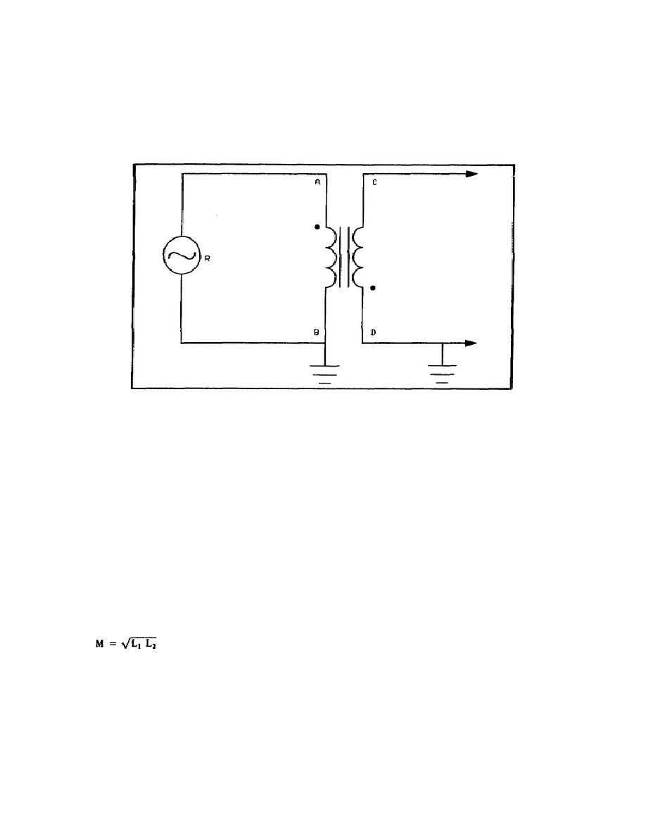
In figure 4-9, the polarity of point C is 180 out of phase with point A. However, if point C were grounded instead of
point D, the secondary voltage, with respect to ground, would be in phase with the primary voltage.
Figure 4-9. Phase Notation of a Transformer with Generator (R).
Mutual Inductance
In the discussion of coils you learned that a changing current through a coil induced a voltage in the coil which was in
opposition to the applied voltage. This process is called self-induction. The ability of the coil to cause self-induction is
inductance. In a transformer, a changing current through the primary induces a voltage in the secondary, and a
changing current through the secondary induces a voltage in the primary. This is mutual induction.
Mutual inductance is a property of a transformer just like inductance is a property of a coil. As with inductance, the
unit of inductance is the henry (h). The symbol of mutual inductance is the letter M. A transformer has a mutual
inductance of one henry if a current change of one ampere per second in one coil induces one volt in the other coil.
The mutual inductance of a transformer is determined by its construction: the type of core, the number of turns in its
coils, and its dimensions. Note that these factors also determine the inductance of coils. When all the lines of force set
up by the primary cut all the turns of the secondary, and vice versa, M can be determined directly from the inductances
of the primary and secondary (L1 and L2). In such a case, there is unity coupling.
86


 Previous Page
