MM0704, Lesson 4
POWER TRANSFORMERS
In power transformers, you can usually distinguish between the high and low voltage windings by the relative diameter
of the wire. The low voltage side has the higher current; therefore, it has the larger diameter wire. You can use
ohmmeter resistance check to identify windings for sure.
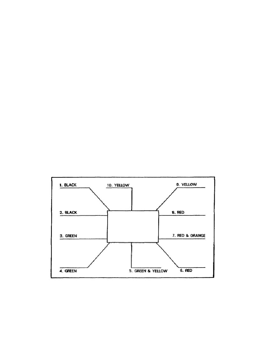
A typical power transformer has color-coded leads so that it is easy to pick out the primary and secondary windings.
Figure 4-17 shows the numbered and colored leads for the transformer. Figure 4-18 in the schematic is for that
transformer. The black leads are the primary; the red leads are the high-voltage secondary winding; and the red and
orange lead is the center-tap. The yellow indicates the 5-V secondary; green indicates the 6.3-V secondary; and green
and yellow is the center-tap. If the leads are not color-coded, they will be numbered on the transformer. Those
numbers will be found in schematics of the equipment.
There are several types of power transformers, from the huge transformer installed in the commercial powerhouses to
the small ones used with radar equipment. Transformers used in radar have a sufficiently low degree of loss to permit
the heat generated to be radiated naturally from the surfaces of the coils and core without exceeding the safe operating
temperature. This class of transformer is called the dry, self-cooling type.
With high-power transformers, the external surfaces of the core and coils are not sufficient to dissipate the heat by
natural radiation and convection. These units are immersed in a tank of oil. The oil conducts the heat from the core
and coil by convection to the surface of the tank wall, where it is dissipated by radiation. This type of transformer is
also in radar equipment.
So far, the power transformers discussed have had only one secondary winding. More often there are several secondary
windings, each providing a different voltage. Look at figure 4-18; it is a schematic of a typical power transformer used
in electronic circuits.
Figure 4-17. Number and Color Coded Power Transformer.
92


 Previous Page
