SM0486
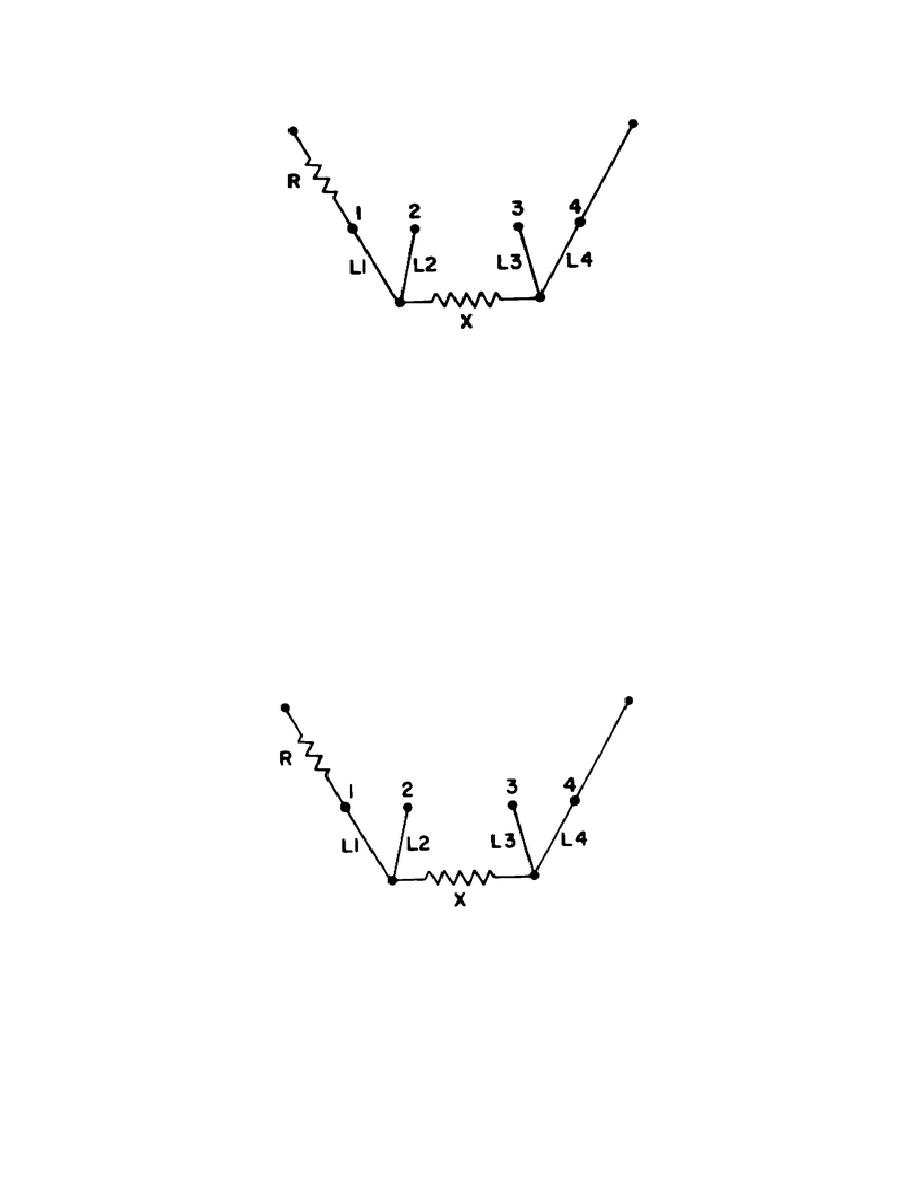
Figure 8.
Mueller bridge four-terminal connections.
i. The last division of the Mueller bridge discussed is shown in figure 8.
The resistor R represents the adjustable rheostat arm labeled "R" in figure 5. The
letter X represents a four-terminal resistance such as the one in the resistance
thermometer.
L1, L2, L3 and L4 are the leads which connect the resistor
(resistance thermometer) to the bridge for a measurement.
j. If the galvanometer is connected to binding post 2, as shown in figure 9,
the resistance X and the lead L4 (with its resistance) are connected into the
right-arm of the bridge.
The lead L1 (with its resistance) is connected in the
adjustable arm R.
k. If the ratio arms A and B are equal resistances and the resistance of L1
is equal to that of L4, the bridge is balanced by adjusting the rheostat arm until
its resistance equals the resistance of the arm in which X is located.
Usually,
leads L1 and L4 are interchanged and the successive readings averaged so that you
can record the reading presented when L1 is equal to L4 with the galvanometer at
its NULL position.
Figure 8.
Mueller bridge four-terminal connections.
1. Measurement principle.
Our primary purpose in discussing the Mueller
bridge is to complete the concept of the resistance thermometer measurement
principle.
16


 Previous Page
