SM0486
of the meter.
The connection is made through the input network.
The four
sensitivity controls are located in the lower center of the panel. The appropriate
control is switched into the circuit being operated by use of the channel selector.
The input network selector S-3 chooses one of three networks to be used with the
operating circuit. The OUT position of the network selector is used to apply the
unfiltered pickup signal directly to the attenuator amplifier. A calibrate signal
switch and potentiometer (s-6 and R-35) taps a portion of the filament supply
voltage to provide the attenuation amplifier with an adjustable calibration
voltage. The voltage regulator for the supply distorts the sine wave; however, the
resultant wave is suitable for setting the gain of the first half of the amplifier.
(3) Operation selector switch S-4 is used in selecting the calibration,
velocity, or displacement function of the meter. In addition, the switch provides
two ranges of sensitivity for each measurement function. Range switch S-2 is a 7-
position attenuator whose setting indicates the full-scale meter reading.
The
reading must be multiplied by the factor indicated on the operation selector.
c. Operation.
As a technician you need to know the relationships existing
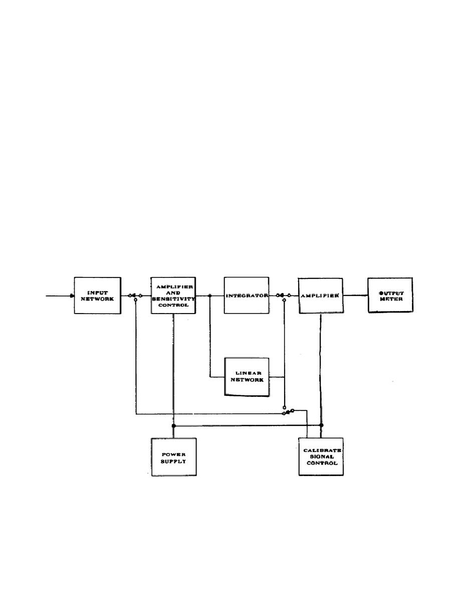
between the panel controls, meter circuits, and operation procedures. The primary
circuits of the vibration meter are shown in Figure 4.
The signal from the
vibration pickup is fed into an attenuation network in such a manner that the
pickup in each channel always looks into a fixed impedance.
Figure 4.
Vibration Meter Block Diagram
112


 Previous Page
