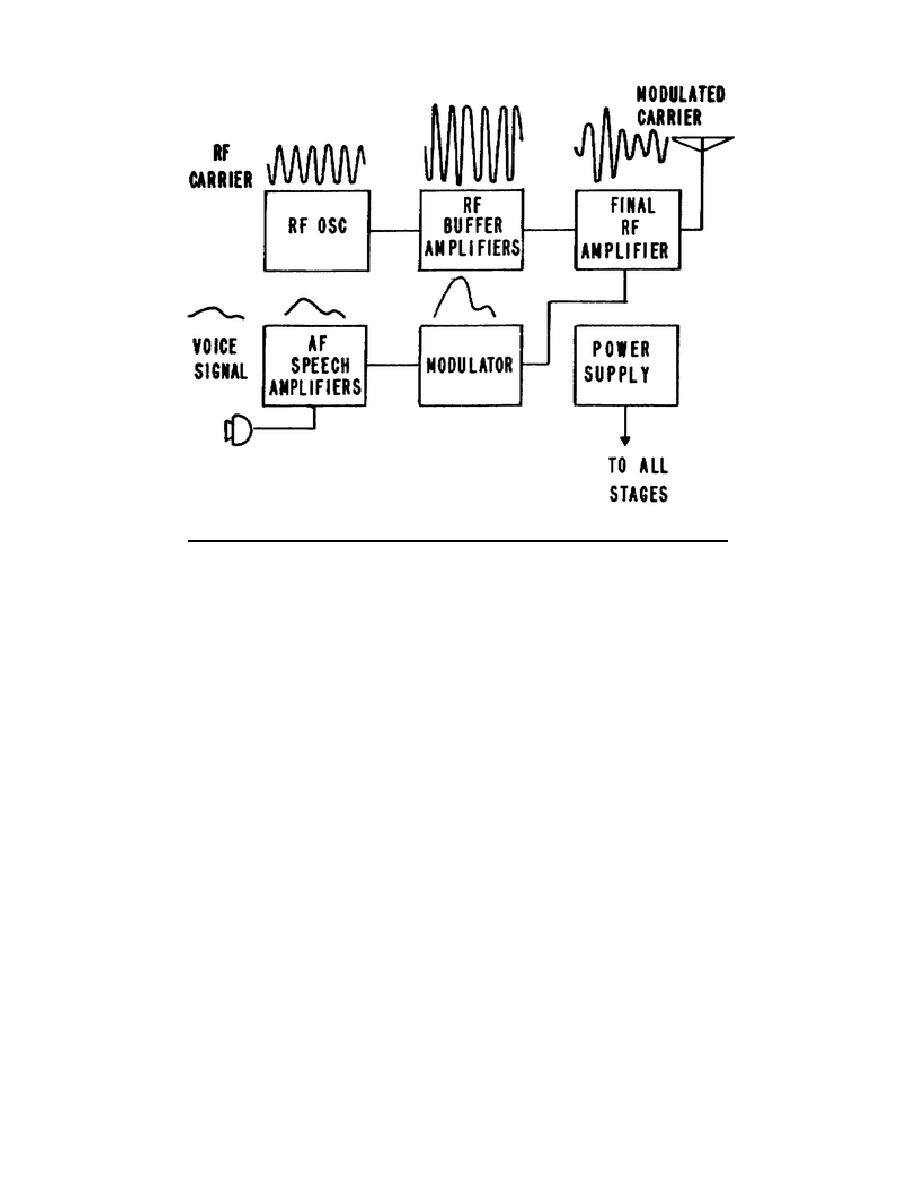
Figure 2-9.
Amplitude-modulated radiotelephone transmitter.
and the modulator, and is used to vary the plate power of the power
amplifier. If the plate power is varied at an audio rate, the output
power varies at the same rate.
The modulating signal determines the
amount of output power that the final RF amplifier will furnish to the
(3) The final RF amplifier produces the composite of the carrier and the
audio signals. Notice in the figure that the amplitude of the carrier
frequency is varying at the audio rate.
(4) A of figure 2-10 illustrates one method of introducing the modulating
AF voltage into the power amplifier.
This method of modulating the
carrier is known as plate modulation. The waveforms in B, C, D, and E
show the effects of modulation.
(5) The modulation occurring in the power amplifier generates sideband
frequencies. Assume that the carrier frequency in B of figure 2-10 is
100 kHz, and the constant-frequency modulating signal shown in C is 1
kHz.
The frequencies appearing in the plate circuit of the power
amplifier are:
100 kHz
100 kHz plus 1 kHz = 101 kHz
100 kHz minus 1 kHz = 99 kHz
1 kHz
The sideband frequencies are 101 and 99 kHz, and the center frequency
is 100 kHz. The carrier wave and sidebands are illustrated in figure
2-11.
309 L2
25


 Previous Page
