MM0704, Lesson 2
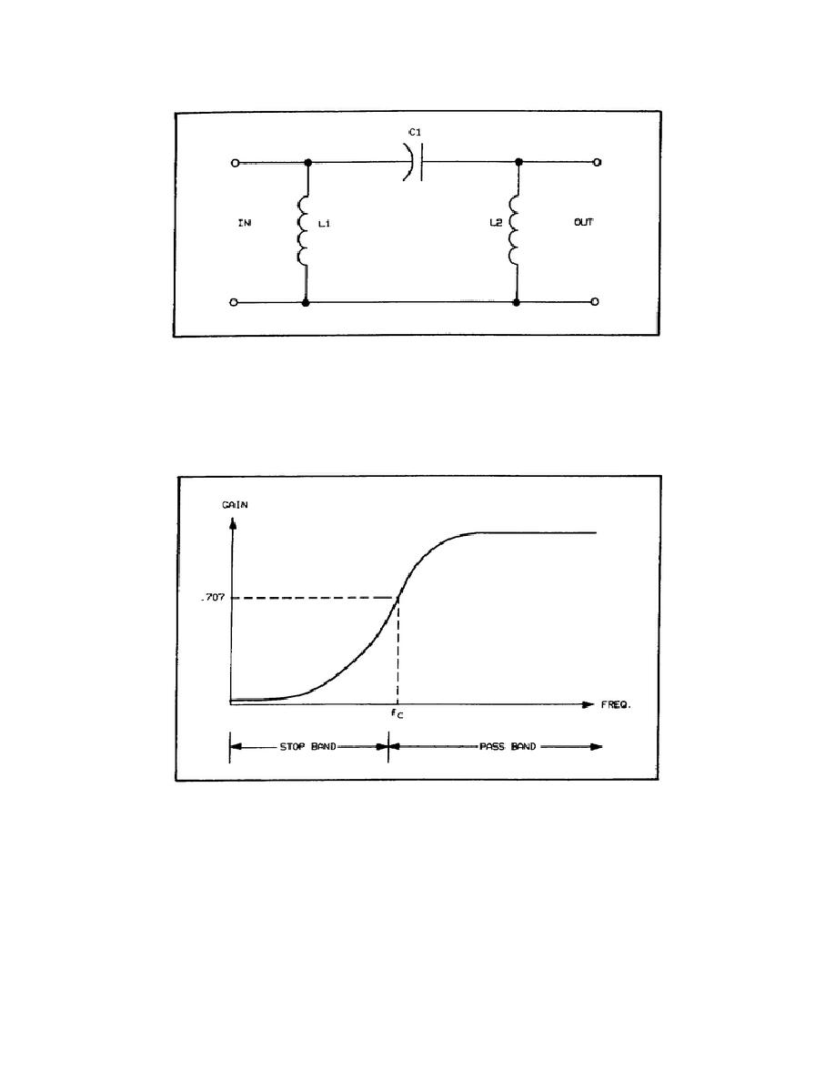
Figure 2-7. -Section, High-Pass Filter.
Transmission Characteristics. By comparing figures 2-4 and 2-8, you can see that the arrangement of the
components in a circuit can completely change its operation. Assume, for example, that the cutoff frequency of the
lowpass filters in figure 2-4 is 10 kHz, interchanging the inductor and capacitor would reverse the stop and pass bands
but leave the cutoff frequency at 10 kHz, as in figure 2-8.
Figure 2-8. Transmission Characteristics of High-Pass Filters.
Band-Pass Filters
Band-pass filters are used where noise over a wide range requires filtering. It restricts all but a small band of
frequencies.
L-section. The use of resonant circuits in filter networks provides a more selective method for filtering. A circuit
consisting of a coil and a capacitor in parallel has an extremely high impedance at its resonant frequency, and
47


 Previous Page
