MM0704, Lesson 3
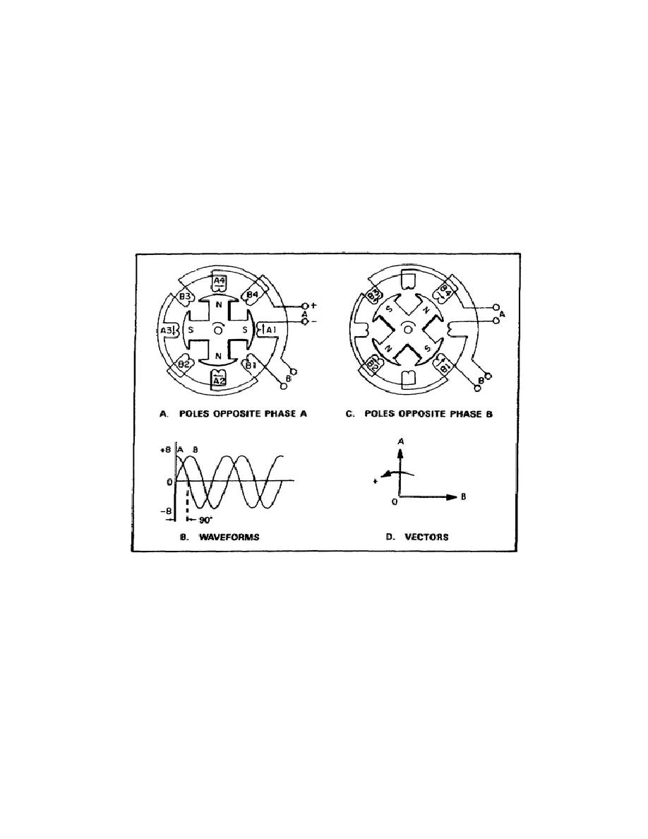
not being cut by flux. This condition establishes the 90 relation between the two phases. Figure 3-13 is a schematic
diagram of a two-phase, four-pole, AC generator. The stator consists of two signal-phase windings (phases)
completely separated from each other. Each phase is made up of four windings which are connected in series so that
their voltages add. The rotor is identical to that used in the single-phase AC generator. In figure 3-13A, the rotor poles
are opposite all of the coils in phase A. Therefore, the voltage induced in phase A is maximum, and the voltage
induced in phase B is zero. As the rotor continues rotating in a clockwise direction, it moves away from the windings
of phase A and approaches those in phase B. As a result, the voltage in phase A decreases from its maximum value and
the voltage in phase B increases from zero. In figure 3-13B, the rotor poles are opposite the windings of phase B. Now
the voltage induced in phase B is maximum, and the voltage induced in phase A has dropped to zero. Notice that in the
four-pole AC generator, a 45 mechanical rotation of the rotor corresponds electrically to one quarter cycle, or 90
electrical. Figure 3-13C illustrates the waveforms of the voltage generated in each of the two phases. Both are sine
curves, and A leads B by 90.
Figure 3-13. Two-Phase, Four-Pole AC Generator.
The three-phase AC generator, as the name implies, has three single-phase windings spaced so that the voltage induced
in each winding is 120 out of phase with the voltages in the other two windings. A schematic diagram of a three-
phase stator showing all the coils becomes so complex, it is difficult to see what is actually happening. A simplified
schematic diagram, showing all the windings of a single phase lumped together as one winding, is in figure 3-14A.
The rotor is omitted for simplicity. The waveforms of voltage are shown to the right of the schematic. The three
voltages are 120 apart and
69


 Previous Page
