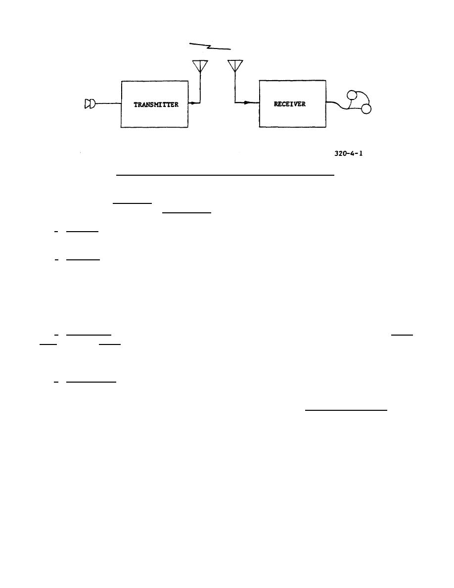
Figure 4-1. Block diagram of a basic radio communication system.
is to be transmitted, a microphone must be used to control the output of the modulator and, hence, the transmitter
output. Such a transmitter is called a radiotelephone transmitter.
e. Radiation. The output of the transmitter is applied to the transmitting antenna whose primary function is
to radiate the energy into space in the form of electromagnetic waves.
f. Reception. A radio receiver has a triple function. First, it selects the desired signal from the great number
picked up by the antenna. Secondly, it removes the intelligence from the RF signal. Thirdly, it amplifies the
audio-frequency (AF) output which in turn causes the loudspeaker to reproduce the sound. Between the signal
selection and detection stages there usually will be an amplifier to raise the weak signal to a higher voltage.
4-2. METHODS OF TRANSMISSION
a. Carrier Wave. The radio signal produced by a transmitter at a fixed frequency is known as the carrier
wave, or simply carrier. It carries no intelligence until it is modulated or changed in accordance with the
intelligence to be transmitted. Upon modulation, it changes in a manner to suit the characteristics of the
equipment used in the system.
b. Radiotelegraph. Radiotelegraph signals are produced by keying a continuous-wave (CW) carrier. The
telegraph key turns the transmitter on and off, resulting in "bursts" of RF signals in accordance with the telegraph
message. The RF signal, being of too high a frequency for the human ear to detect, is made audible in the
receiver by mixing the incoming CW signal with a signal generated locally by a beat-frequency oscillator (BFO).
Since both incoming and BFO signals are in the RF range, they are inaudible. However, the combination of the
two produces a third signal, which is audible. Thus each time the key is depressed at the transmitter, a tone is
heard from the receiver headset.
(1) Intelligence is conveyed from transmitter to receiver by means of the international Morse code. CW
transmission uses a very narrow
36


 Previous Page
