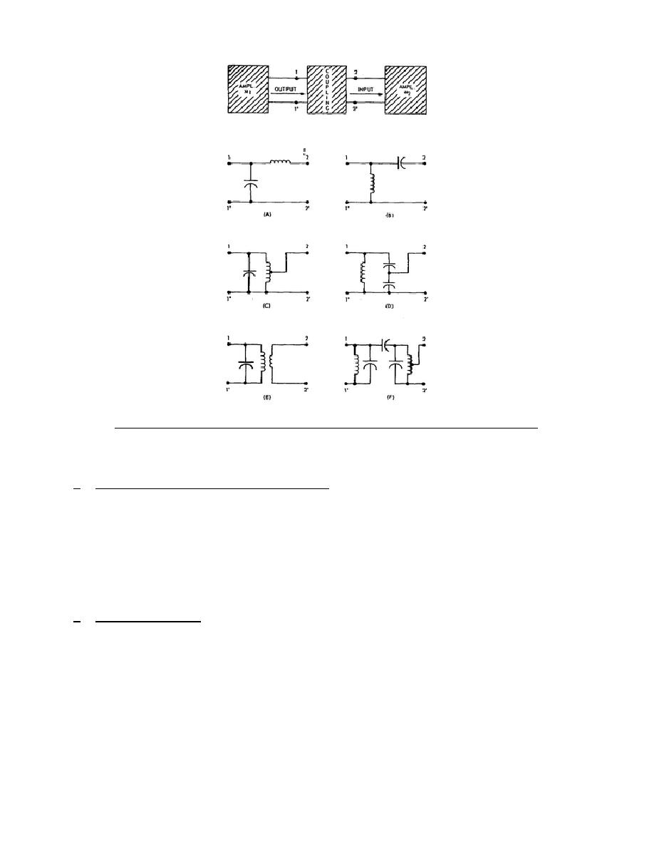
Figure 1-1.
Tuned coupling arrangements for RF and IF amplifiers.
small, it is possible to make the Q of the resonant circuit high, thereby obtaining
good selectivity and the required high impedance between points 1 and 1'.
d. Coupling for Common-Emitter Circuits. For coupling common-emitter amplifiers
whose input resistance is comparatively high, circuits C through F are more
suitable. In circuit C, the low output impedance is matched to the input impedance
of M2 by tapping the tank inductance. In circuit D, the desired impedance match is
obtained by tapping off between capacitors of properly proportioned values.
Circuit E illustrates matching by the step-down action of a transformer from a
tuned primary to an untuned secondary of fewer turns.
Lastly, circuit F shows a
double-tuned capacitively coupled network. Note that the inductance is tapped for
the proper impedance to match that of the input of M2. Better selectivity can be
obtained by using this network because both output and input can be tuned.
e. Coupling Summary.
There are numerous interstage coupling schemes possible.
Only the more important ones that can be designed to meet the selectivity and
matching requirements ordinarily encountered have been presented in this attached
memorandum.
Special circuits and devices can be employed for extraordinary
requirements.
4


 Previous Page
