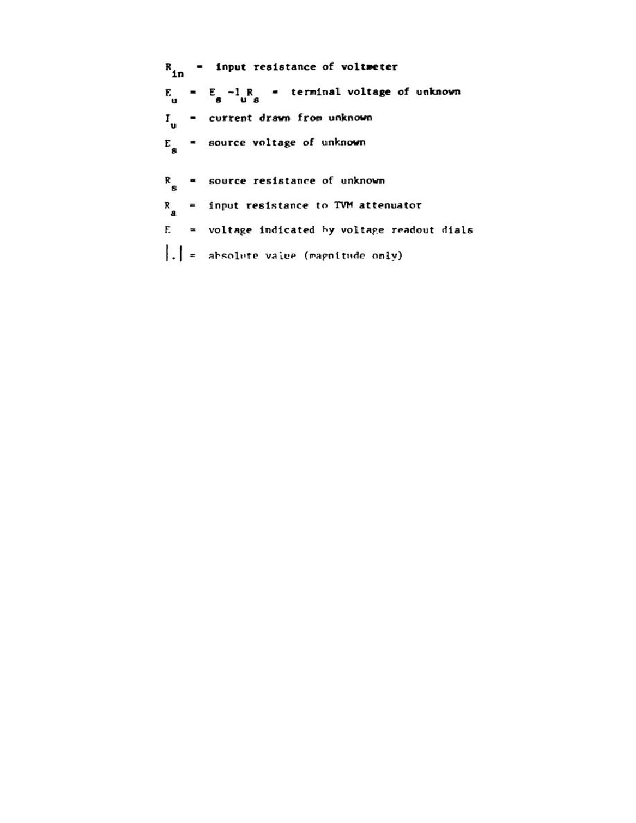
(1) Thus, the input resistance is essentially infinite (leakage
resistance across the input is in the order of 1012 ohms) at null when E is
equal to Eu and Es.
For the 100- and 1000-volt range, the dc input
attenuator is always connected across the input terminals. Thus, the input
resistance is equal to the resistance of the dc input attenuator which is 10
megohms.
(2) The input impedance for the AC TVM and AC differential mode
depends on the input impedance of the ac to dc converter and its attenuator.
The ac input impedance is thus 1 meghom and 40 picofarads.
g. The chopper drive circuit (figure 5-15 (fo)) determines the chopper
timing frequency of 84 Hz. The circuit is symmetrical with the transistors
biased so that they can conduct simultaneously.
However, cross-coupling
capacitors C105 and C106 force Q106, Q109 and Q107, and Q108 to conduct
alternately. This results in a square wave varying from about 0 to 6 volts
that drives chopper coil C201. The symmetry and frequency of the waveform
are adjusted with R126 and R124 respectively.
h. The voltage for null detector amplifier stages, Q201 through Q205,
is supplied by the same -18 volt power supply that is used to power the 0-
to 11-volt reference (fig 5-15).
The voltage for chopper drive circuit
transistors Q106 through Q109 is obtained from a half-wave rectifier
consisting of diode CR101 and an R-C filter network (R105 and C101) that
supplies 6 volts dc.
Current-determining resistors R238 and R240, diodes
CR201, and CR202, and divider resistor R239 provide a compensating voltage
for the purpose of adjusting the null detector to zero with R239 when there
is no signal input.
Diode CR201 keeps one side of R239 at approximately
+0.6 volt dc with respect to the null detector common while diode CR202
keeps the other side at approximately -0.6 volt dc.
i. The only ac voltage component that will reduce the accuracy of the
887A is one that either saturates the null detector or one that beats with the
112


 Previous Page
