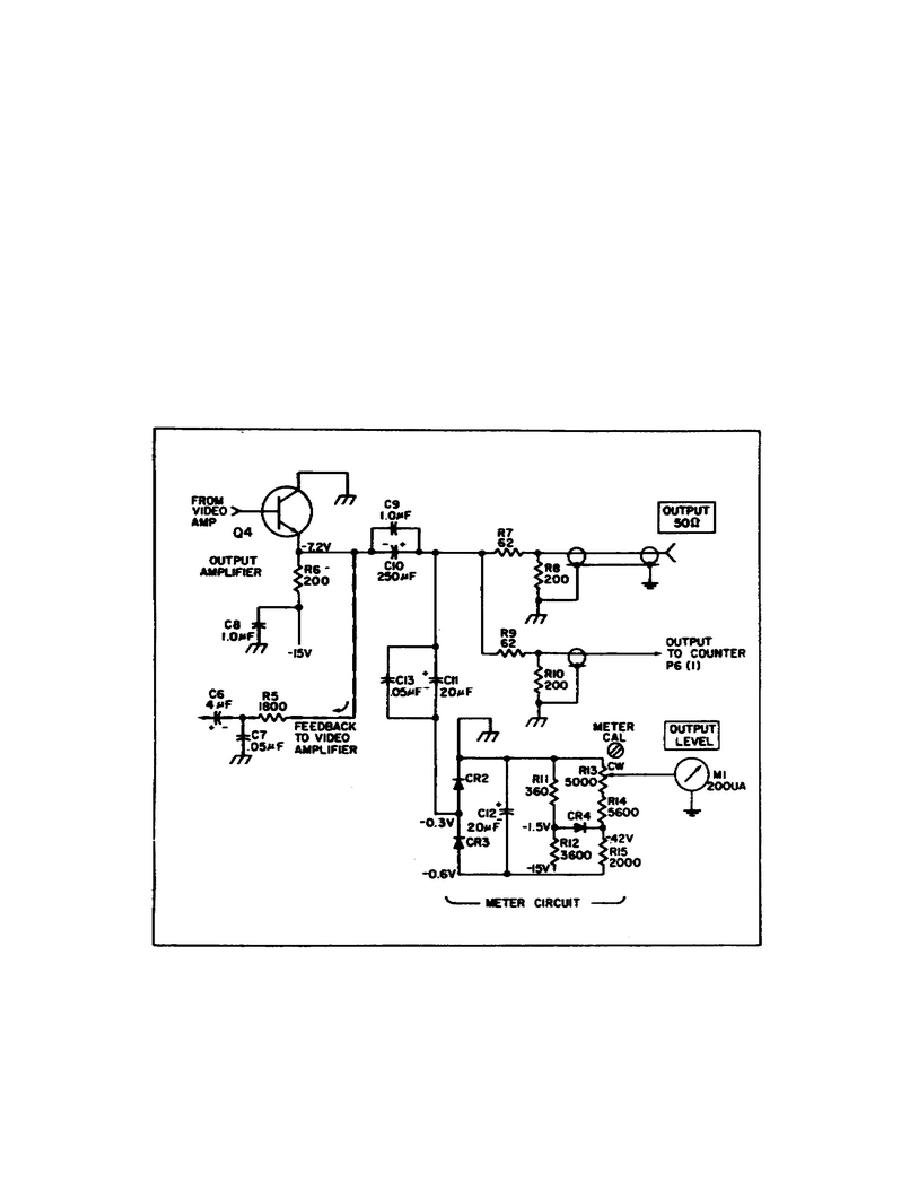
Positive feedback from the emitter of Q4 to amplifier no. 2 in the video
amplifier increases video amplifier gain at higher frequencies. Capacitors
C9 and C10 are connected in parallel to improve the overall frequency
response.
The signal at Q4 emitter is rectified by CR2 and CR3 and filtered by
C12.
This resultant dc is supplied to Output Level meter M1.
Capacitors
C11 and C13 are connected in parallel to improve the frequency response of
the meter circuit. Meter Cal potentiometer R13 provides an adjustment for
calibrating the meter. Minus 15 volts is supplied to the meter circuit and
establishes a bias on diodes CR2 and CR3.
This prevents the meter
indicating for very small output signals and permits a meter indication in
the green scale for an output signal greater than 100 millivolts. Diode CR4
acts to protect the meter during input signals greater than 100 millivolts.
The CR4 anode is clamped at about -1.5 volts, which corresponds to
approximately full scale.
When the rectified signal output exceeds this
value, CR4 conducts and protects the meter.
Figure 7.
Output amplifier.
89


 Previous Page
