9.
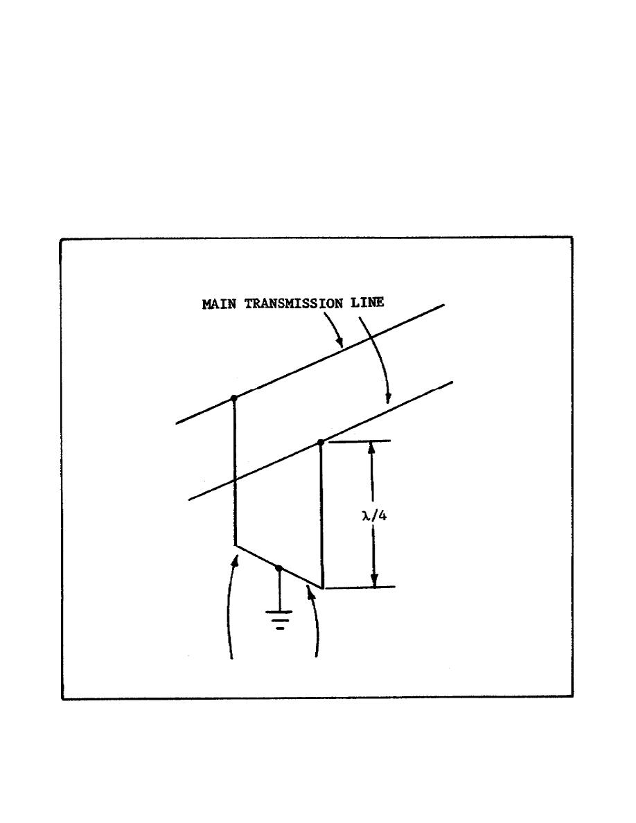
Assume that the quarter-wave section of transmission line shown in
Figure 43 is being used as a supporting stub for the main transmission
line. The impedance reflected back to the main transmission line at
the fundamental frequency will resemble the impedance that is provided
by a
a.
parallel-resonant circuit.
b.
series-resonant circuit.
c.
capacitor.
d.
resistor.
Figure 43.
Quarter-Wave Section Transmission Line.
53


 Previous Page
