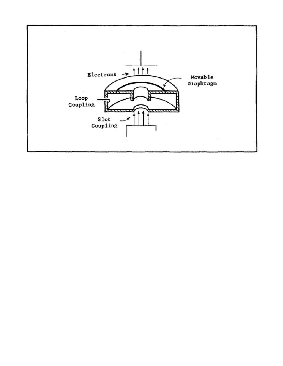
Figure 99. Resonant Cavity.
6.
What adjustment can be made to the resonant cavity shown in Figure 99
to cause its resonant frequency to decrease?
a.
Extend the coupling loop further inside the cavity.
b.
Move the diaphragm to decrease the height of the cavity.
c.
Adjust the diaphragm to increase the height of the cavity.
d.
Rotate the coupling loop so that it is perpendicular to the
magnetic field.
7.
To obtain the maximum output from the resonant cavity shown in Figure
100, the coupling loop should be placed at point
a.
A and parallel to the magnetic field.
b.
B and parallel to the magnetic field.
c.
C and perpendicular to the magnetic field.
d.
D and perpendicular to the magnetic field.
149


 Previous Page
