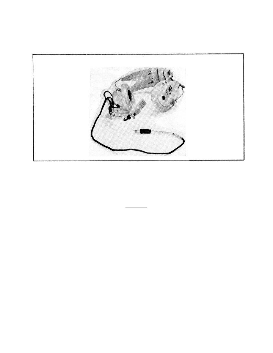
g. Headset-microphone H-101( )/U (Figure 7). The headset part of the
H-101( )/U will be used to check the audio output from the R-1496( )/ARN-89(
).
Figure 7.
H-101( )/U.
3.
To connect the equipment, turn to page 3-11 of the TM 11-5826-227-34
extract.
There you see a diagram of the correct way to connect your
equipment.
Using Figure 3-5 as a guide, connect your equipment.
Do not
forget that certain equipment called for in the extract, has been replaced
by new equipment.
CAUTION
ENSURE THAT ALL EQUIPMENT
POWER
SWITCHES
ARE IN THE OFF POSITION.
4.
Take a break and have the training supervisor check your equipment
connections. Then, proceed to Learning Event 2. If you had any problems,
talk them over with your training supervisor.
Learning Event 2:
TROUBLESHOOTING RADIO RECEIVER R-1496( )/ARN-89( )
1.
The troubleshooting procedure used to find a defective subassembly is
made up of a basic test and eight subtests. The results of the basic test
will tell you what subtest to do.
The basic test may show you what
subassembly is faulty. You will never have to do all eight subtests. In
most cases, you will only have to do the basic test and one subtest to find
the problem.
8


 Previous Page
