MM0704, Lesson 1
where the voltage across the resistor is proportional to the current through it, and the voltage across the capacitor is
proportional to the capacitive reactance, XC.
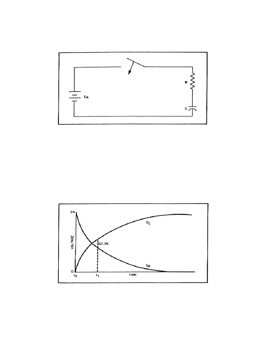
Figure 1-12. RC Circuit.
The instant the switch is closed, in figure 1-12, the voltage across the capacitor is zero and the voltage across the
resistor is EA. After a period of time, the transient action will be complete, the capacitor voltage will be EA, and the
resistor voltage will be zero. Figure 1-13 shows the relative values of resistor voltage and capacitor voltage as time
elapses.
RC Time Constants. The value of C determines the amount of electron displacement required for a given voltage, and
the value of R determines the rate of electron displacement. Therefore, the time from T0 to T1, in figure 1-13, is
determined by the value of R and C in the circuit. The time constant of the RC circuits is the length of time required
for the capacitor to charge to 63.2 percent of the applied voltage. In other words, at T1 the capacitor charge has
reached 63.2 percent of its final charge.
Figure 1-13. Voltages in the RC Circuit During the Charging Period.
19


 Previous Page
