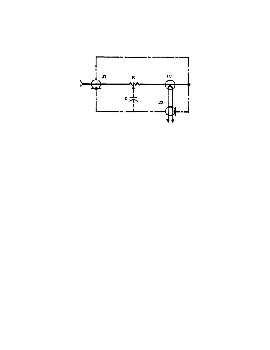
A UHF coaxial connector (J1) is provided for input and a G-R type connector (J2) is
provided for thermocouple output. The thermocouple leads are not connected to the
case in order to maintain signal isolation. Lower voltage probes have capacitive
compensation (C) from the body of the resistor to ground to provide as flat a
frequency response as possible.
Figure 2-13.
Model 1395 schematic
3. The thermocouple heater pf the Model 1395 can withstand continuous overloads of
50 percent (to 7.5 mA) and momentary overloads of 100 percent (to 10mA). Overloads
greater than these can result in a permanent change of thermocouple characteristics
or burnout of the heater.
Burnout occurs so rapidly that the rise in DC couple
output cannot be detected. Therefore it is necessary to take every precaution to
avoid overloading the thermocouple.
a. Be sure the voltage being measured is reduced to its lowest value before
connecting or disconnecting the Model 1395 input.
b. Provide a method for monitoring or controlling the voltage being measured.
c. Do not change the frequency of the voltage being measured without first
reducing the voltage to its lowest value.
d. Do not allow the open-circuit DC couple voltage to exceed 16 millivolts
(equivalent to 7.5 mA of heater current).
e. If reverse DC measurements are made, to eliminate the effect of reversal
errors, the DC source must be operated ungrounded since one end of the thermocouple
heater is grounded in the Model 1394.
4. Voltage measurements are made with the Model 1395 Coaxial Thermal Converters
by using the principle of AC to DC transfer.
An unknown AC voltage applied
to the input of a Model 1395, chosen to have a voltage range appropriate
for the measurement, will cause a rise in temperature of the thermocouple
heater proportional to the RMS value of the AC voltage.
This temperature
rise will in turn produce a DC couple output proportional to the square
33


 Previous Page
