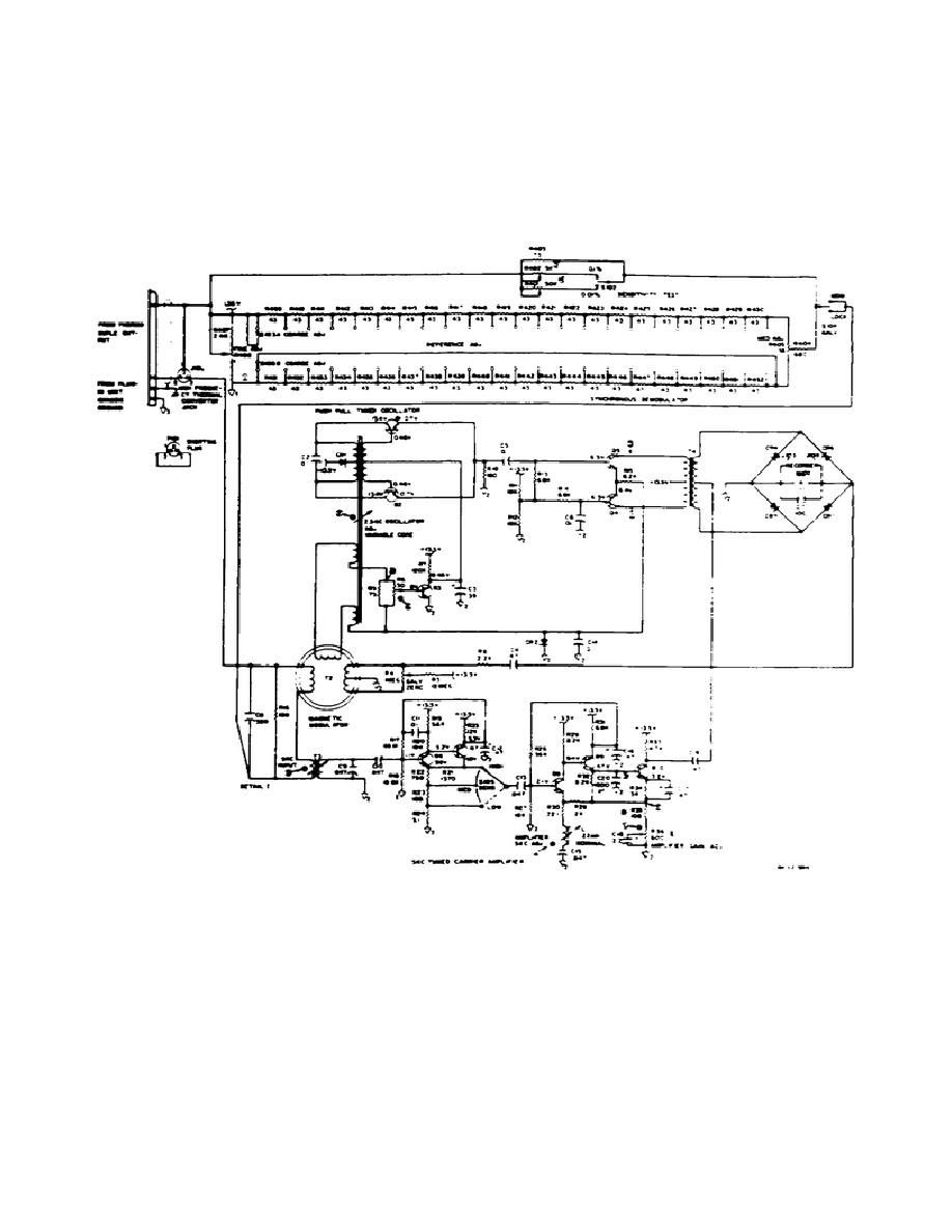
n. Push-pull oscillator and frequency doubler in the nulling circuit (fig 2-
10) consists of Transistors Q1 and Q2 which oscillate at a frequency of 2.5 kHz as
determined by C2 and T1.
Transformer T1 is adjustable and is used to set the
operation frequency of the instrument.
Transistor Q3 is used to control the
amplitude of the oscillator output. The output of the oscillator, appearing across
R10, peaks at 5 kHz rate and is used to drive the synchronous demodulator. The 2.5
kHz signal from the oscillator is fed to the magnetic modulator from windings on
transformer T1.
Figure 2-10.
Nulling circuit
(1) The magnetic modulator has been designed in such a manner as to produce
a 5 kHz output. This 5 kHz output is proportional in level to the DC input of the
magnetic modulator and its phase is dependent on the direction of the input
current. R4 is the front panel zero adjust used to balance the modulator. The 5
kHz signal from the magnetic modulator is fed to transformer T3 which is the input
for the tuned carrier amplifier.
29


 Previous Page
