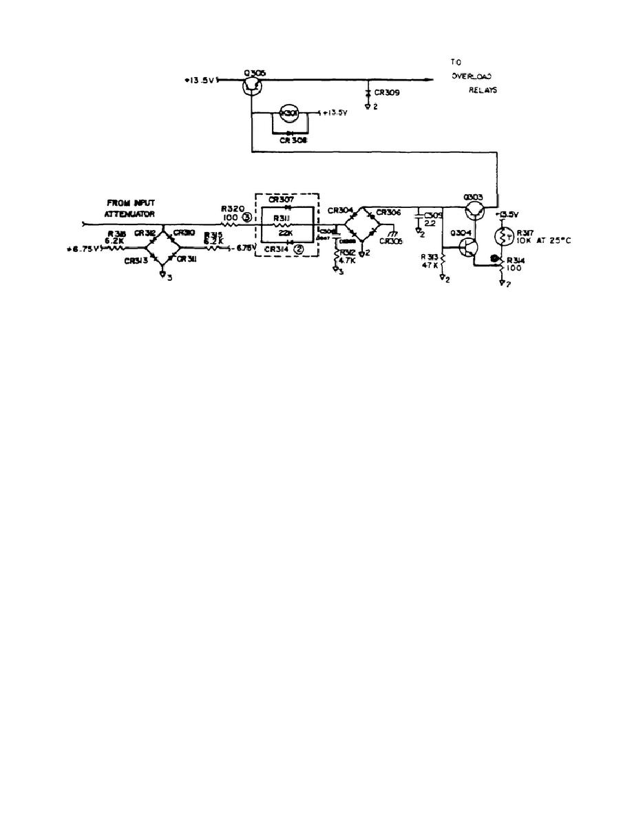
Figure 2-7.
k. The thermocouple element has been tested and selected at the factory and
placed in an insulating case with a standard octal plug base.
The thermocouple
element is the high vacuum, insulated type with a nominal output of 7 millivolts at
rated input. The Model A54 unit will have to be rechecked for calibration accuracy
if the thermocouple is replaced. The input to the thermocouple may be reversed by
operating the POLARITY switch located on the front panel of the Model A54 plug-in
unit.
With this switch it is possible to check the turn-over error of the
thermocouple with a minimum of effort.
l. When using the transfer standard it is not necessary to measure the output
voltage of the thermocouple, it is necessary only to provide a means of detecting
and comparing the thermocouple output accurately when making transfer measurements.
A variable voltage source has been designed into the Model 540B which fulfills the
stability and resolution requirements for this application. Referring to Figure 2-
8, the adjustment of the REFERENCE ADJUST controls COARSE, MEDIUM and FINE will
vary the voltage at point b, from zero to approximately 14 millivolts.
The
MOMENTARY position on the GALV switch makes it possible to search out and find an
approximate null on the galvanometer with the COARSE control without applying a
steady overload to the galvanometer. The LOCK position allows a fixed path for use
while adjusting the MEDIUM and FINE controls to maintain the galvanometer balance
in successively more sensitive ranges.
27


 Previous Page
