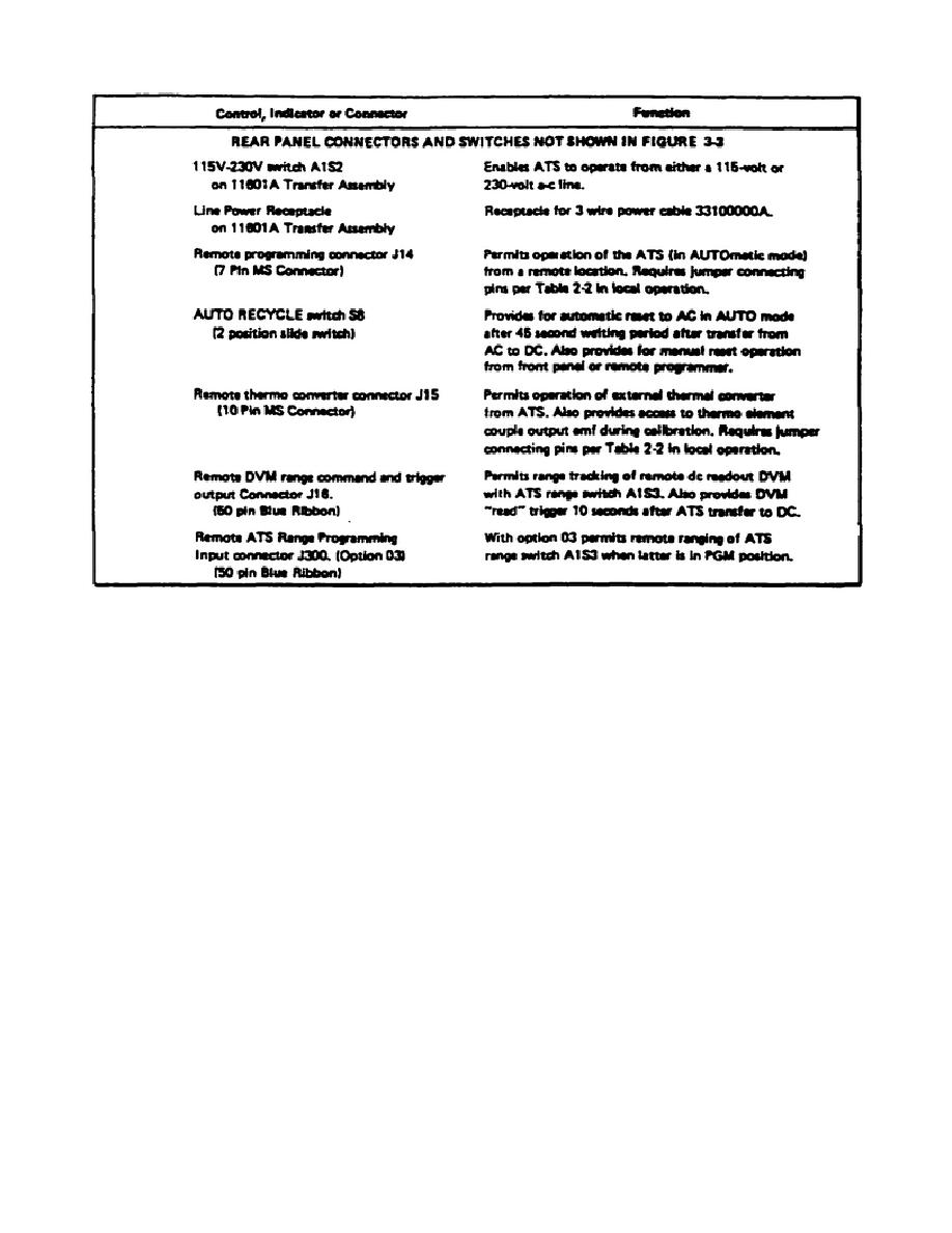
Table 3-1.
Controls, indicators, and connectors (cont.)
e. Various sources of error may be present when employing the ATS.
These
sources are detailed below so that the user may be familiar with them and allow for
them to obtain maximum accuracy.
(1) Loading effects.
The input impedance of the ATS, particularly on the
low voltage ranges, is relatively low (due to the current required for the
thermoelement heater and the shunt input capacity presented by the relay connected
range attenuator) and will have a loading effect when connected to the voltage
source under test. Voltage sources having a nonzero output impedance and/or poor
regulation characteristics will develop two different output levels; one while the
ATS is in the AC balancing state (loading the source) and a second when the ATS is
in the DC transfer state (voltage source removed from ATS input attenuator). The
output voltage of the ATS, as indicated on the readout instrument, will be the
voltage of the loaded source.
(2) Losses in interconnecting wiring.
Since the ATS has an output
interconnecting the voltage source and the ATS may introduce a measurement error,
particularly when the low voltage ranges are employed.
It is recommended that
short heavy leads be employed when interconnecting the equipment.
46


 Previous Page
