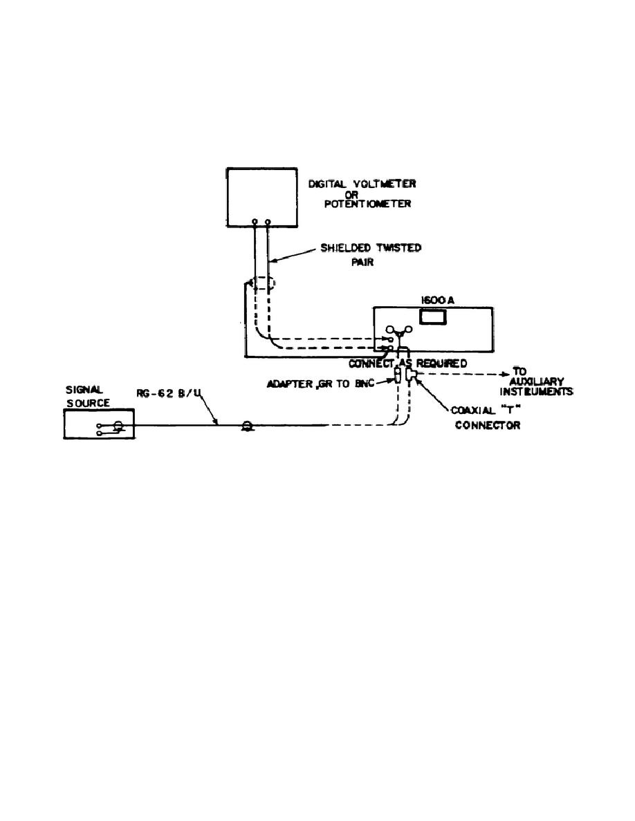
d. Interconnect the equipment as illustrated in Figure 3-4, coupling the
voltage source under measurement to the AC INPUT 32-1000V connector.
Set input
voltage and RANGE VOLTS switch into range.
e. Note which indicator (AC or DC) is illuminated.
If the DC indicator is
illuminated, momentarily press the TRANSFER-RESET pushbutton switch.
The AC
indicator will illuminate and the DC indicator will extinguish.
Figure 3-4.
Equipment interconnection diagram
f. Note if the OVERLOAD PROTECTION PUSH TO RESET indicator is illuminated.
If it is, momentarily depress the OVERLOAD PROTECTION PUSH TO RESET pushbutton
switch. The indicator will extinguish.
g. Adjust the MANUAL BALANCE COARSE and/or FINE controls to obtain a meter
indication of 0 on the BAL scale.
When this indication is obtained, the ATS is
ready to be set to the DC output state.
To increase resolution at balance, push
NULL X5 pushbutton.
This gives maximum resolution of 10 ppm per minor scale
division.
h. Momentarily depress the TRANSFER-RESET pushbutton switch to place
the
ATS
in
the
DC
output
state;
the
DC
indicator
should
illuminate.
A DC output voltage equivalent to the RMS value of the signal under measurement
can be obtained from the indication of the digital VM or potentiometer
connected between the +DC OUTPUT and -DC OUTPUT binding posts.
Note that a less
50


 Previous Page
