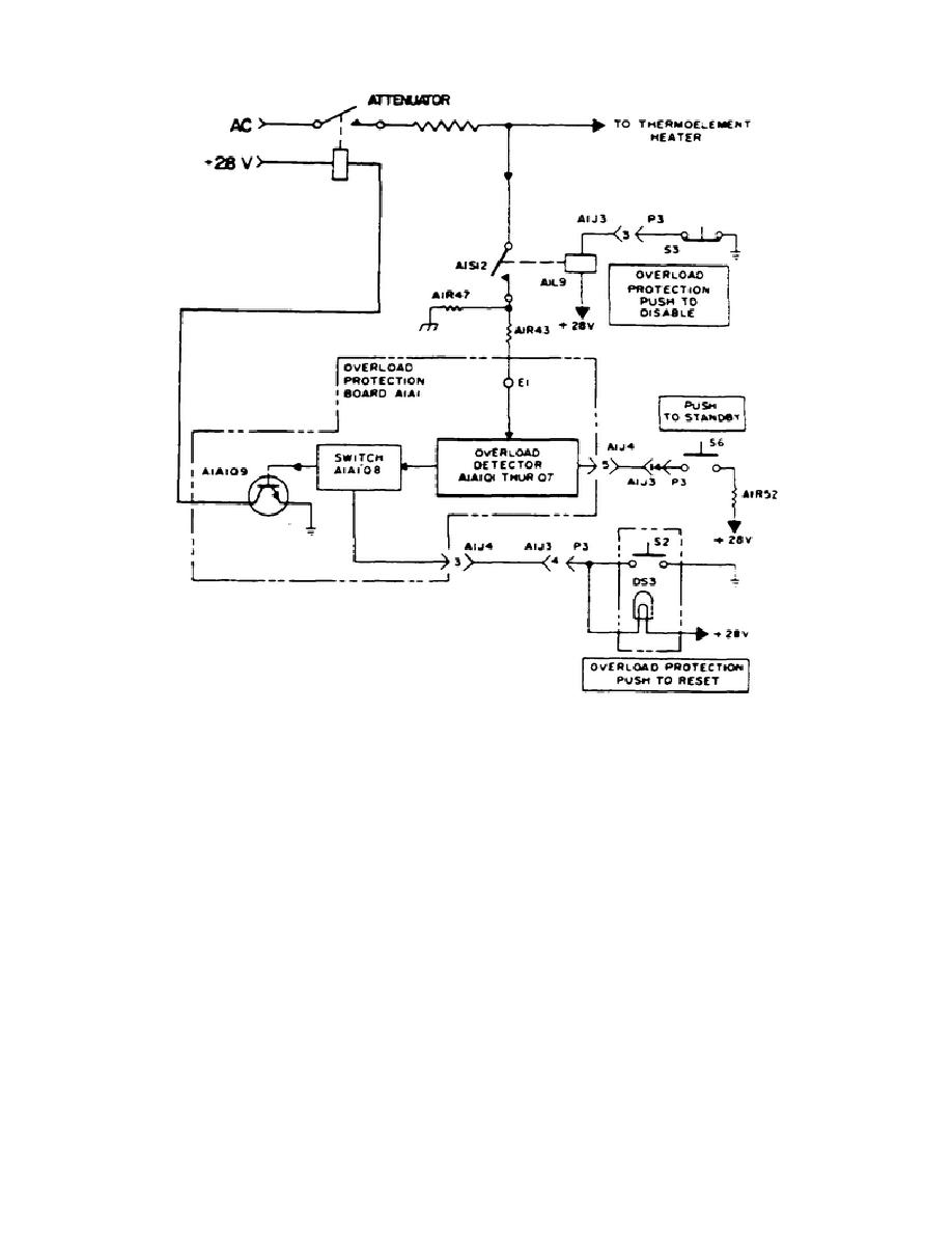
Figure 3-7.
Model 1600A simplified input circuitry
2. When the mode selector switch is set to MANUAL BALANCE and the AC indicator is
illuminated, the operator adjusts the settings of the MANUAL BALANCE COARSE and
MANUAL BALANCE FINE controls until the voltage at the input to the chopper is 0
volts.
At this point, the front panel indicates a null.
When the operator
momentarily depresses the TRANSFER-RESET pushbutton switch, the DC indicator
illuminates and the output of either the low or high voltage amplifier is coupled
to the same attenuator and the applied AC signal under measurement is disconnected.
Since the output of the applicable voltage amplifier was 0 volts at the moment of
transfer, the thermoelement output will decrease immediately after the transfer.
This results in the generation of an error voltage which is fed to the chopper.
The polarity of this error is such as to cause the amplifier to drive the
thermoelement so that the error voltage is reduced to zero.
At this time the DC
output of the voltage amplifier, which is present at the DC OUTPUT binding posts,
is equal to the RMS value of the applied AC signal.
55


 Previous Page
