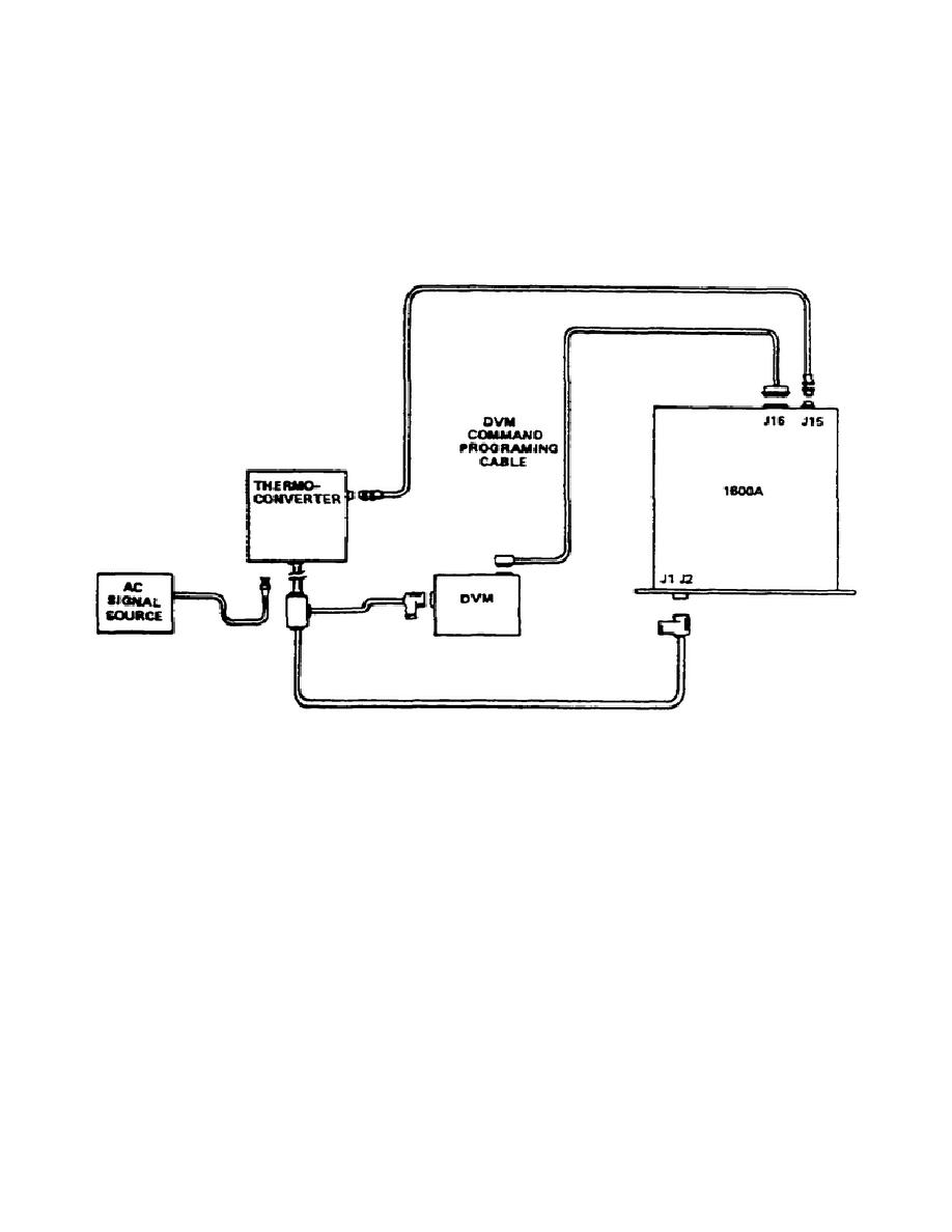
5. External thermal converters, such as the Model 1395, may be used with the ATS
for extended frequency range to 1 GHz.
The ATS is set up for this mode of
operation simply by removing P15 and J15 at the rear panel and connecting a
suitable cable between J15 and the thermal converter DC output (fig 3-5). To make
a transfer reading, connect the unknown AC source being measured to the input of
the thermocouple. Balance the AC loop in the usual way, depending on the mode of
operation of the 1600A.
When the DC transfer has taken place, disconnect the
unknown AC source from the thermocouple and quickly connect the free end of the DC
output cable to the thermocouple.
Allow 10 to 15 seconds for the DC loop to
stabilize and read the DC voltage on the DVM.
Figure 3-5.
External thermal converter connection
53


 Previous Page
