MM0474
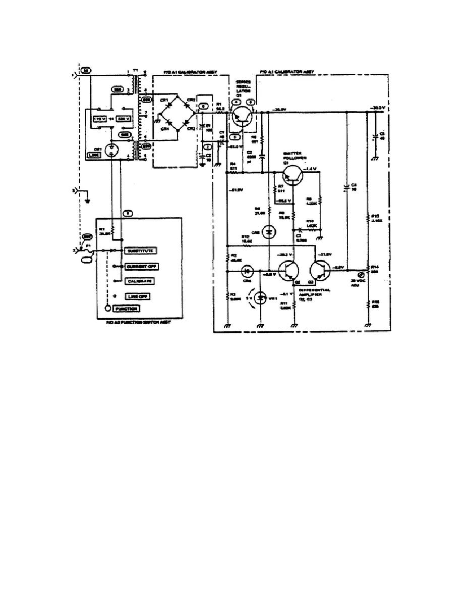
Figure 6.
Power supply schematic.
consider A1CR6 to be placed back in the circuit. The purpose of A1CR6 is to
initially provide a negative voltage at the base of A1Q2.
When the power
supply is turned on, a negative voltage appears at the junction of A1R2 and
A1R3.
The negative voltage forward biases A1CR6 and allows it to conduct.
Thus, the negative voltage is applied to the base of A1Q2, allowing it to
conduct. In turn, the base-emitter junction of the emitter follower, A1Q1, is
forward biased and it also conducts.
This action forward biases the base-
emitter junction of the series regulator, Q1, which conducts, causing its
collector voltage to increase negatively toward -30 volts. This action places
more negative voltage on the cathode of A1CR5 causing it to conduct.
Conduction of A1CR5 supplies an increasingly negative voltage to the base of
A1Q2. This process is regenerative and the base voltage of A1Q2 continues to
increase negatively until it is held at -9 volts by A1VR1.
92


 Previous Page
