MM0474
operating range of each mount, and the results recorded on the label of the
mount. In addition, each mount is tested on a swept-frequency basis to assure
that interpolation between measured points is valid.
(7) A detection thermistor is mounted within the mount's shorted
waveguide section and is located so that it samples the E field and provides an
optimum match across the band. As it absorbs RF power, its temperature (and
therefore its resistance) attempts to change. However, the RF bridge circuit
is self-balancing and reduces thermistor bias current to maintain the
thermistor's proper operating resistance. Since the amount of bias change is
proportional to incoming RF power, it is measured and used to indicate the RF
power absorbed by the mount.
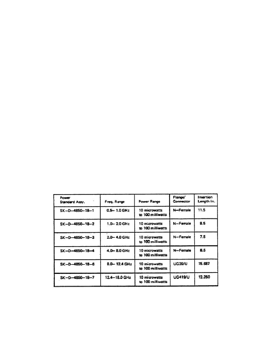
b. Specifications.
The following tables provide the specifications for
the power standard assemblies and directional couplers which are used in the
assemblies.
The specification for individual thermistor mount is covered in
lesson 3. Table 5 shows which directional couplers and thermistor mounts go
into the individual power standard assemblies, and the assembly number is
provided for reference.
(1) Not
separately
specified.
Variation
allowed
is
included
in
accuracy.
(2) About mean coupling which is the average of maximum and minimum
coupling in the rated frequency range.
(3) Port A is main line input, Port B is main line output, and Port C is
secondary line output.
Table 3.
Specifications
131


 Previous Page
