SM0486
b. The pulses are counted by an electronic counter such as a 524B.
With the counter set up to count for a specific period of time, the number of
pulses counted can be converted to rpm. Let's consider an example where 600 pulses
are counted during a period of exactly 10 seconds, from a disc that has six
reflecting segments.
If 600 pulses were counted during 10 seconds, 3600 pulses
would be counted during 1 minute. However, since there are six reflecting segments
on the disc, we must divide 3600 by 6. Thus, the shaft is rotating at 600 rpm. As
you can see by this example, if the disc has six reflecting segments and the pulses
are counted for 10 seconds, the readout is in rpm.
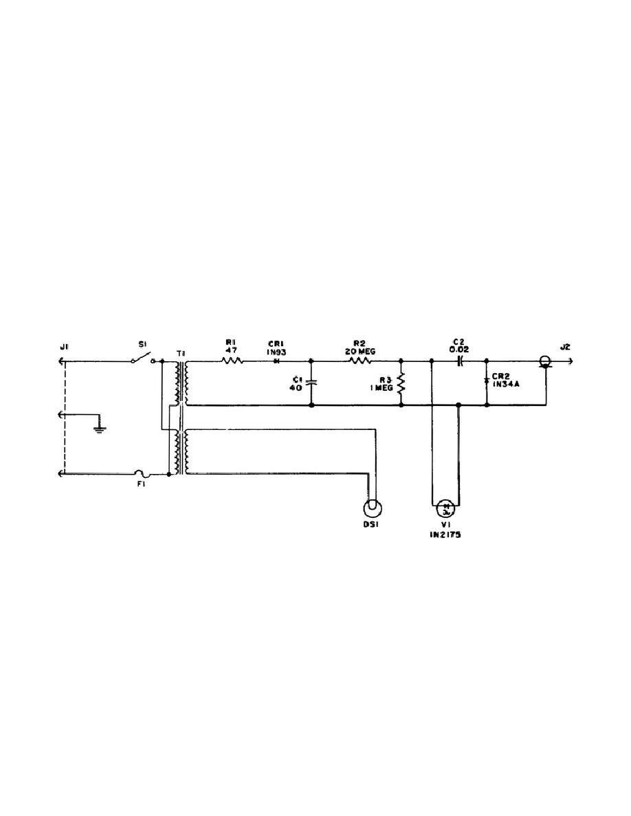
c. A schematic diagram of the optical tachometer is shown in Figure 6.
When switch S1 of this circuit is closed, the l10-volt, 60-cycle AC applied to J1
causes voltages to be developed across the secondaries of transformer T1. One of
the secondaries develops the voltage for the light and its beam illustrated as DS1
sort of threshold voltage across photocell, electrical impulses are developed and
passed by way of C2 and J2 to the electronic counter.
The amplitude of the
electrical pulse varies from 3 volts rms for an object rotating at 180 rpm to 2
volts rms for a rotation speed of 200,000 rpm.
Figure 6.
Optical tachometer schematic diagram
d. To calibrate this tachometer, you replace the rotating element,
shown in Figure 5, with a rotating device whose rpm is known.
You apply the
tachometer output pulses to a frequency standard (counter) whose input impedance is
at least 1 megohm. The high-input impedance minimizes the effects of loading. The
frequency counter (standard) readings should agree with the rpm settings of the
rotating device (standard).
84


 Previous Page
