SM0486
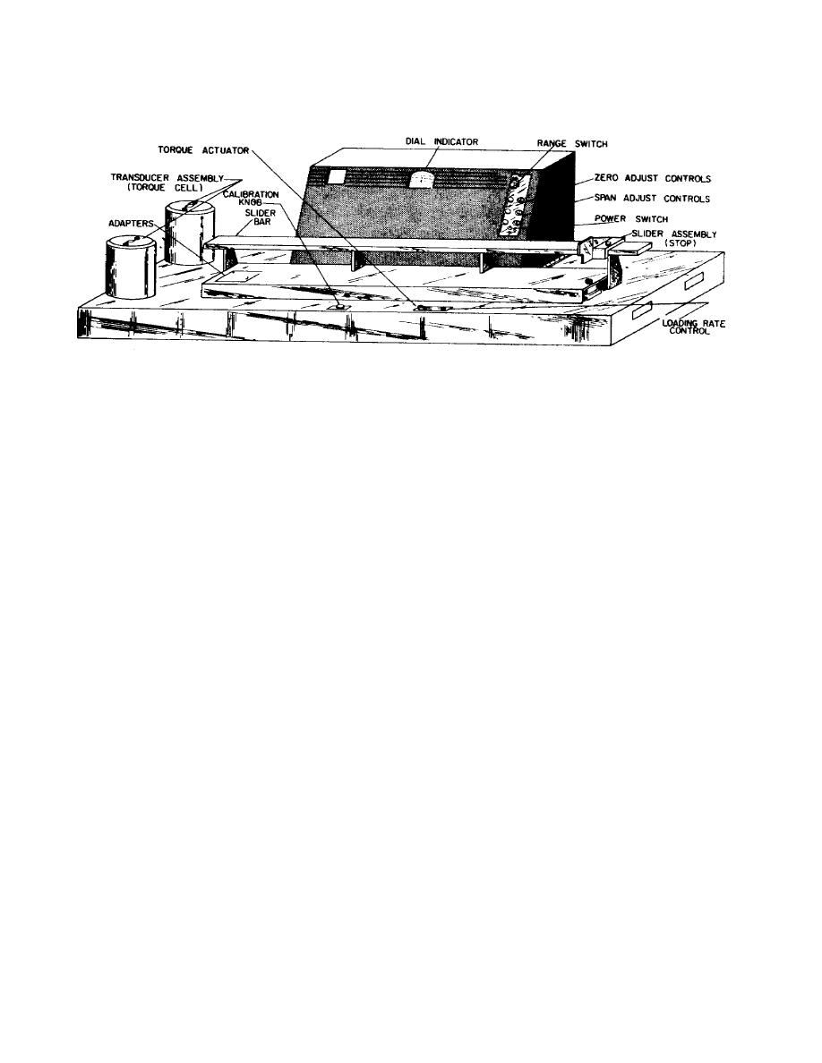
Figure 9.
Baldwin 4 Operation Controls and Indicators
b. Figure 10 shows how and where various forces are applied when the torque
tester is operated and the direction which the resulting forces take.
Figure 10
also shows how the adjustable stop may be positioned on the slide bar to
accommodate torque wrenches of different lengths.
(1) As is shown in Figure 6, the torque application system consists of a
pneumatic section which applies a controlled force and a mechanical section which
converts this force to a measurable torque.
The piston and cylinder assembly is
the main component of the pneumatic section. Piston movement is regulated by three
control valves series-positioned in the cylinder air line.
These valves are as
follows:
A rate control valve, which regulates the flow
of
incoming
air
and
consequently the rate of piston shaft movement.
An actuator valve, which directs the regulated air into the piston cylinder
or vents the piston cylinder to atmosphere.
A holding valve, which can stop piston movement by sealing off the cylinder
supply.
93


 Previous Page
