SM0486
(4) When you place the actuator valve lever in the APPLY position,
pressurized air is introduced into the piston and cylinder assembly, causing the
piston rod to move out at the desired rate of speed, as indicated by the arrow in
Figure 10.
The piston rod movement, in turn, is transmitted to the SR-4 torque
cell through the connecting torque lever so that the resultant force is as
indicated by the arrow.
The result is a strain or torquing action of increasing
the stationary-held torque wrench is mounted on the torque cell. The strain on the
cell and torque wrench continues to increase until you move the actuator valve
lever to the RELEASE position or close the holding valve.
(5) When you test preset wrenches, there is a temporary slack in strain as
the torque wrench slips at its preset value, but even in this case, the strain
continues to be exerted until one of the two previously mentioned valve positions
is changed.
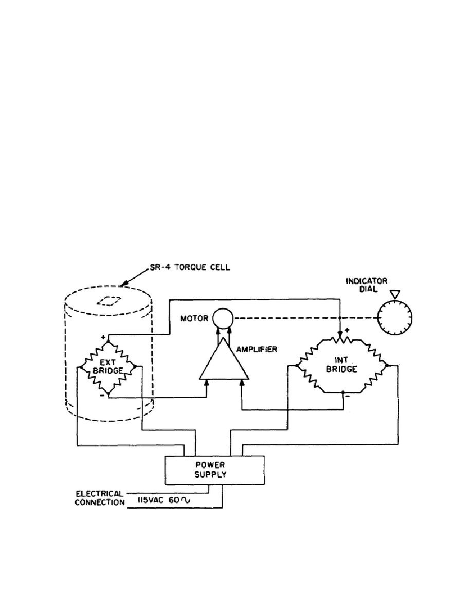
c. Torque measuring system. The
torque measuring system, as shown in Figure
11, is basically a simple Wheatstone
bridge circuit complete with amplifier and
power supply.
A motor driven dial
indicator and slidewire assembly are also
included to form a null-balance type of
measuring system.
Figure 11.
Torque Measuring System Schematic Diagram
95


 Previous Page
