c.
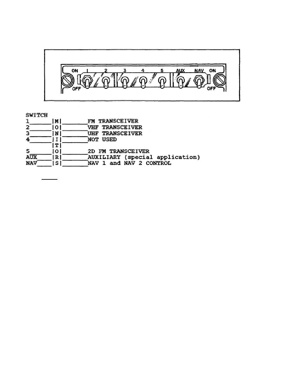
The seven toggle switches (S3-S9) across the top front of the C-6533 are used to
monitor any of eight audio input signals. (See Figure 3.)
Figure 3. RECEIVER SELECTOR switches.
NOTE:
Remember, although the SELECTOR switch also monitors transmission, it
monitors only one transceiver at a time.
Learning Event 2:
THEORY OF OPERATION OF C-6533
1.
BLOCK DIAGRAMS. The C-6533 has three operational modes. These are the ICS
mode, the radio transmit mode, and the receiver monitoring mode.
a.
ICS mode. (See Figure 4.) All communication controls in an aircraft are
connected to an interphone line. When an operator's PUSH-TO-TALK switch is operated in
the interphone (ICS) position, microphone amplifier AR1 of the operator's communications
control is turned on, and its output is applied to the interphone line through relay K1.
Operation of the PUSH-TO-TALK switch also decreases the operator's sidetone signal level.
Signals on the interphone line, including the operator's voice signals, pass through the mixing
resistor network to VOL control R34 and to headset amplifier AR2. The output of the headset
amplifier is applied to the operator's headset through transformer T4.
4


 Previous Page
