b.
Radio transmit mode (see Figure 5): When an operator operates the PUSH-TO-
TALK switch to the transmit (RADIO) position and SELECTOR switch S1 is set in position 1, 2,
3, 4, or 5, microphone amplifier AR1 is turned on and transmit relay K1 is energized. The
microphone amplifier audio output is applied to the selected transmitter audio output line
through transformer T2, transmit relay K1, level adjust control R29, and SELECTOR switch S1.
Level adjust control R29 is set to provide an audio level of 0.4-volt for modulation of the
transmitters. Operation of the PUSH-TO-TALK switch also applies a control or keying signal
(ground) to the selected transmitter through SELECTOR switch S1 and relay isolator CR9.
Setting SELECTOR switch S1 to a transmitter position also connects the associated receiver
audio line (1, 2, 3, 4, or 5) to the headset amplifier AR2 through a mixing resistor network and
volume control R34. The output is then applied through transformer T4 to the operator's
headset. Sidetone signals are received on this circuit and indicate an overall operative
system.
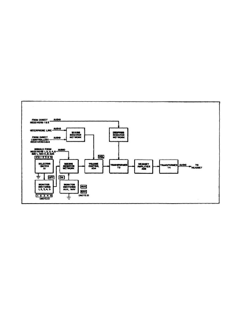
Figure 6. Receiver audio monitoring, block diagram.
c.
Receiver monitoring mode. (See Figure 6.) The signals from a particular
receiver are monitored when S1 is set to position 1, 2, 3, 4, or 5. In addition, seven toggle
switches on the communications control permit monitoring of any eight receiver
6


 Previous Page
