(b)
COMM CONT NUMBER 1 VOL CONTROL: Fully clockwise.
(c)
COMM CONT TEST: OFF.
(d)
DC POWER switch: OFF.
(2)
Using the ME-26 (R X 10 scale), measure the resistance between terminals E5
and E4 on COMM CONT 2 (see page 3-16, TM 11-5821-262-35). Normal reading would be
30 ohms. If you get a higher reading, switch the leads on the terminals. Since we are
checking a diode (CR13), you should get a reading that is much higher in the reverse direction
than the positive direction (30 ohms, approximately). If your reading was high in both
directions, you would replace CR13 and repeat the functional test. Your indication should be
approximately 30 ohms in a forward direction.
(3)
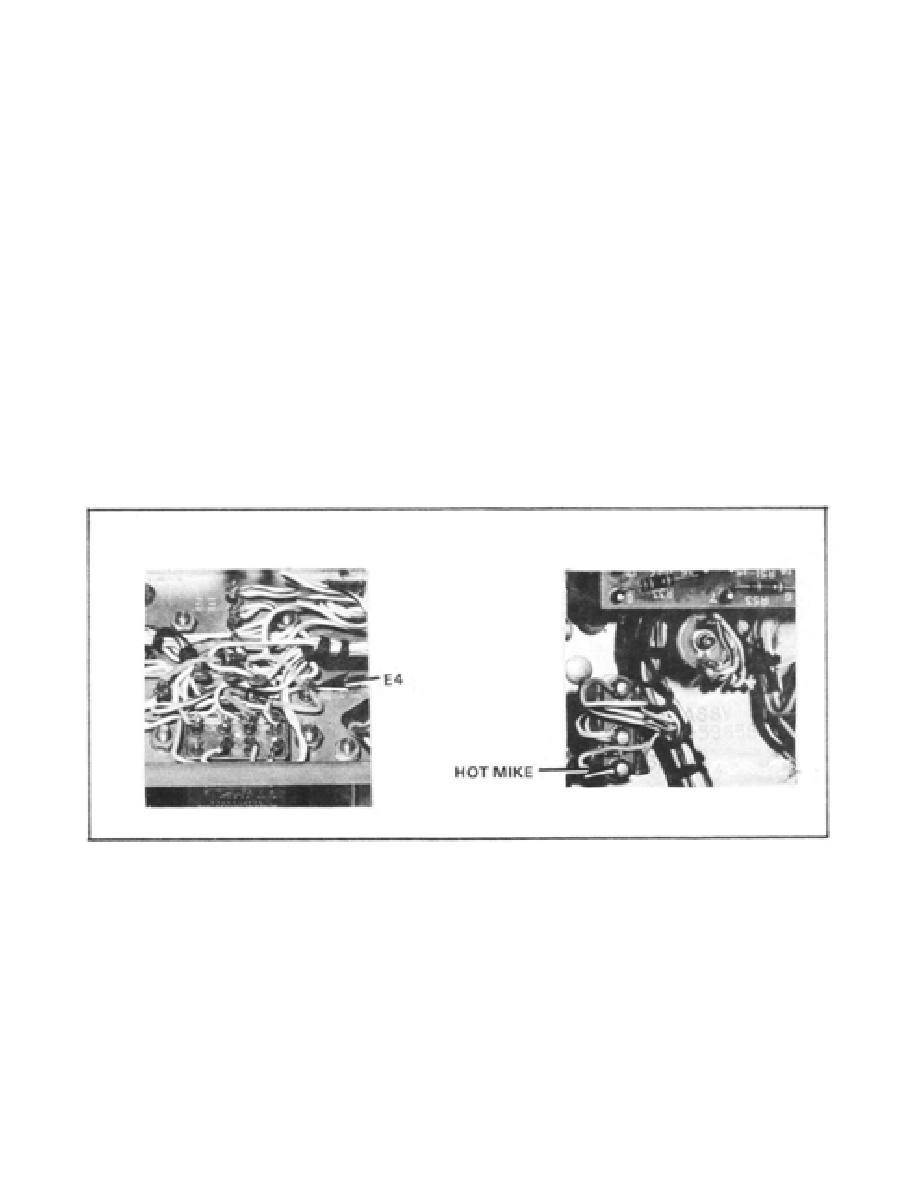
The HOT MIKE switch test is the next step in Subtest 2. To do this we must set
COMM CONT 2 HOT MIKE switch to the OFF position. Using the ME-26, measure the
resistance between the HOT MIKE switch S2 and terminal E4. (See Figure 8.) A normal
indication would show a short and you would continue with the subtest. If the reading is not
normal, replace the HOT MIKE switch and repeat the functional test.
Figure 8. HOT MIKE switch test.
(4)
To perform the next step in Subtest 2 make the following equipment settings.
(a)
COMM CONT TEST switch: Position 1.
23


 Previous Page
