2.
The removal of the faulty part/component assembly should always be performed with
the correct tools and equipment.
a.
Use the correct size soldering iron when the job requires unsoldering a
component or assembly (25-watt maximum).
b.
Before starting your unsoldering procedure, always use appropriate safety
glasses or goggles.
c.
When removing the solder:
(1)
Solder should be removed from terminals and solder cups either by using
mechanical vacuum devices or by wicking with a stranded conductor or shielding braid and
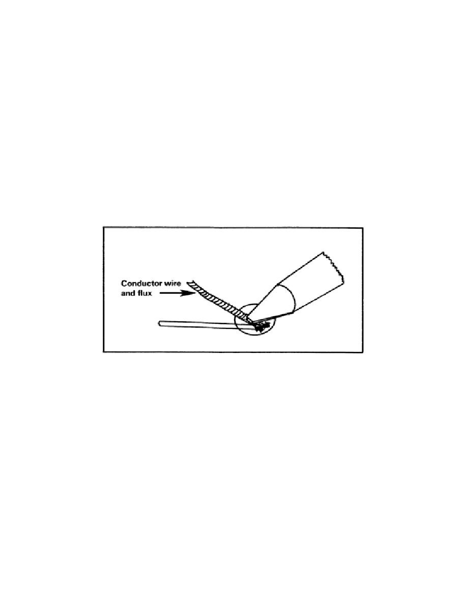
flux. In wicking with stranded conductor or shielding braid and flux, place the wire on the
solder connection and place the hot soldering iron tip on the wire. The iron tip and the wire
shall be removed simultaneously as soon as the desired amount of solder has wicked into the
stranded wire. Remove all residual flux and contaminants. (See Figure 12.)
Figure 12. Wicking operation.
(2)
Surfaces of printed boards with connections to be unsoldered. Unsoldering
operations shall be accomplished in such time and manner that the printed board material or
components are not degraded or damaged.
(3)
Rework the solder connection clean and prepare all reworked solder
connections. All connections shall meet original soldering requirements.
d.
Some components and assemblies are socketed or connected via wire bundle
and electrical connector.
36


 Previous Page
