signals, and keeps the receiver sensitivity fairly level since it reduces stage
gain.
The amplifier operates essentially as a class A stage, with the collector
output signal appearing across the primary of transformer T2. The ac component of
the collector current is induced in the secondary of transformer T2. This output
transformer also serves as the input transformer of the following IF amplifier
stage.
c. Choice of IF.
A commonly used IF in transistor radio sets
is 262 kHz,
because greater gain and more stability can be obtained when the
receiver is
designed to operate with a lower IF than the 455 kHz commonly found
in electron-
tube receivers.
However, the lower IF has the disadvantage in that
it makes the
receiver more susceptible to image frequency pickup.
3-2.
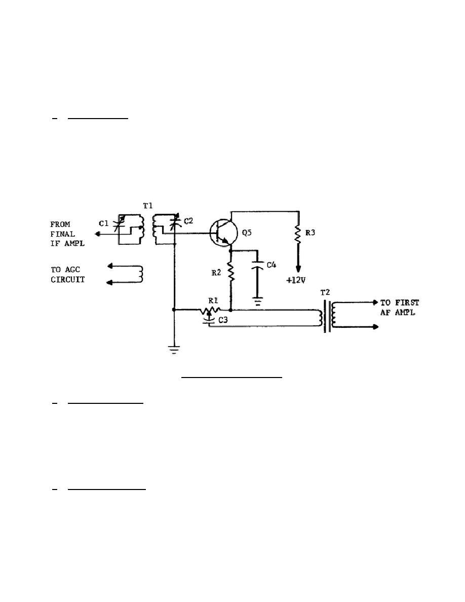
TRANSISTOR DETECTOR CIRCUIT
(fig.
3-2)
Figure 3-2.
Detector.
a. IF Input Circuit. The IF signal is applied to the base-emitter junction of
the transistor through transformer T1, which is physically the output transformer
of the final IF amplifier stage.
Since there is no forward-biasing network, the
stage remains cut off until a signal is applied to it. During the positive half of
the signal, a small current flows through base-emitter circuit R1 and R2. A larger
collector-emitter current flows through R3, R1, and R2. During the negative half
of the signal there is no current flow.
The IF components of the signal are
removed by filter capacitor C4, which will not pass the audio signal fluctuations.
b. IF Output Circuit. IF voltage for use in the AGC circuit is taken from
a third winding (tertiary winding) on transformer T1.
322 L3
18


 Previous Page
