(1) Emitter-follower action accounts for the phase of the signal across R4.
This action also accounts for the fact that input impedance is desirably
higher than ordinary and the output impedance is lower to match the input
impedance of the push-pull stage.
Another advantage offered is the
improved frequency response. Better frequency response can be attributed
to two things: degenerative (negative feedback) action and capacitive
coupling.
(2) We took care to say capacitive coupling rather than RC coupling, since
crystal diodes CR1 and CR2 are used in place of resistors.
These are
discharge diodes that prevent capacitors C1 and C2 from taking on a charge
that would bias the push-pull amplifier well below cutoff.
Inasmuch as
the transistors draw base current during half a cycle for class B
operation, rectified base currents flow into C1 and C2.
If CR1 and CR2
were not connected in the circuit as shown, a negative charge would build
up to reverse-bias the push-pull transistors.
This would correspond to
grid-leak biasing of electron tubes.
To preclude this unwanted base
biasing, CR1 conducts whenever C1 becomes negative with respect to ground,
and CR2 conducts whenever C2 becomes negative with respect to ground.
Thus, these discharge diodes function to maintain 0 volt base bias.
3-6.
COMPLEMENTARY SYMMETRY CIRCUIT
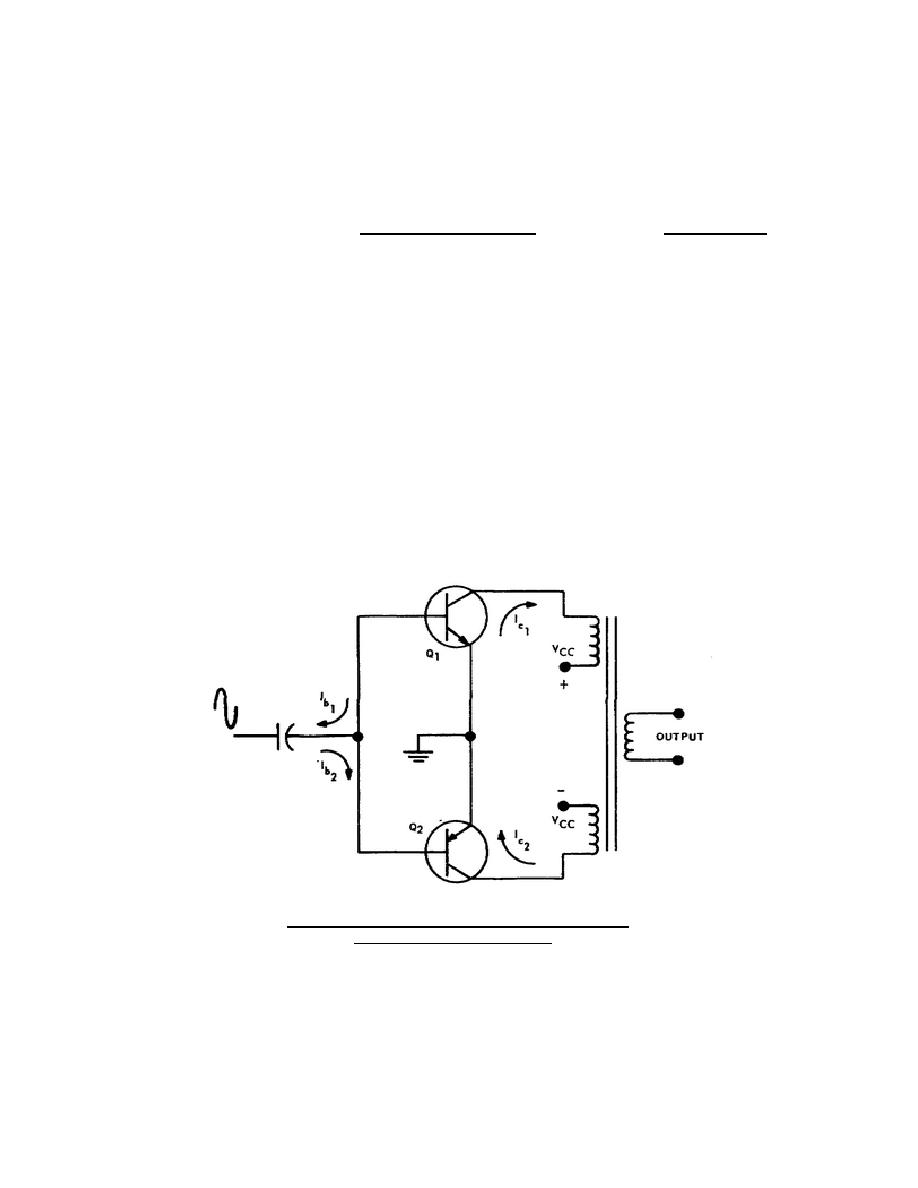
A complementary symmetry circuit arrangement is made possible by the use of an
NPN and a PNP transistor. This simple push-pull amplifier circuit shown in figure
3-8, affords the benefits of capacitive coupling, yet does not require a phase
inverter nor discharge diodes.
Figure 3-8. Push-pull amplifier using
complementary symmetry.
30


 Previous Page
