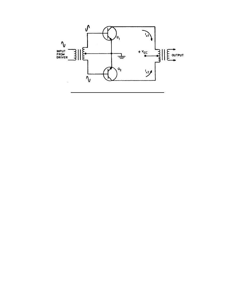
Figure 3-2.
Class B push-pull amplifier.
and remain cut off during negative alternations.
Since their inputs are
180 out of phase, Q1 is conducting (Icl) while Q2 is cut off, and Q2 is
conducting (Ic2) while Q1 is cut off. In other words, Q1 and Q2 conduct
alternately to supply output current (Icl + Ic2) throughout the entire
cycle.
(3) This circuit arrangement amounts to having two symmetrically arranged
single-ended amplifiers supplying a common load.
Sketch A in figure 3-3
is a dynamic curve of a single-ended amplifier; sketch B is the dynamic
curve of a push-pull amplifier. Note that the curve in sketch B is merely
the combination of the dynamic curves of two single-ended amplifiers.
Because of the 180 phase relationship of the input and the circuit
arrangement, the positive direction of base currents Ibl and Ib2 are
opposite; also, the positive direction of collector currents Ic1 and Ic2
are opposite.
The input signal wave is projected on the dynamic curve
diagram in C of figure 3-3.
The output waveshape is a composite of
current Icl and Ic2. This diagram illustrates clearly the faithfulness of
signal reproduction, thus fidelity.
Note the distortion that occurs as
the signal approaches and passes through zero.
This is called crossover
distortion and causes odd harmonics of the signal frequency to appear in
the output signal.
(4) Crossover distortion can be eliminated by biasing Q1 and Q2 in the forward
direction.
A simple biasing arrangement is illustrated in figure 3-4.
Resistor R is made variable so that we can adjust the bias for class AB
operation or class A operation.
If properly adjusted for class AB
operation, the crossover effect is not evident in the output.
A
comparison of A in figure 3-5 and B in figure 3-5 shows why this is so.
The nonlinearity is effectively canceled and excellent fidelity achieved.
If R is adjusted for class A operation, the output waveshape is the
resultant of the individual waveshapes as illustrated in C of figure 3-5.
26


 Previous Page
