c. Effects on Gain. Unfortunately, the current gain of the transistor used in a
multiplier circuit decreases as the frequency and current increase.
This causes
difficulty in obtaining the desired conduction angles at the higher frequencies.
Hence, the collector-current pulses may be broadened because of the random times
taken for the holes to diffuse through the base region, and the tops of the pulses
may be rounded because of the decrease of the current amplification factor (afe)
with emitter current.
These effects are difficult to evaluate; therefore, as a
practical matter, an experimental approach is usually made to obtain the best
operating conditions.
Assume that a transistor is driven, at the base, and the
self-bias for the transistor is controlled by a variable time-constant circuit.
The phase angle of the collector current can be altered by changing the amplitude
of the drive and by changing the time constant. The load impedance can be varied
in the collector circuit to effect the optimum transfer of power. If a chain of
frequency multipliers is to be used, each stage must be capable of driving the
following one.
The use of push-pull stages is advantageous with odd-frequency
ratios, while the push-push connection is helpful with even ratios. The use of two
transistors per stage effectively doubles the power output.
3-2.
MULTIPLIER CIRCUIT CHARACTERISTICS
a. Operating Potentials.
The frequency multiplier, shown in figure 3-1, is a
simple, low-level class C amplifier employing the type of dc stabilization that is
normally used with class A stages. The zero signal operating point, 15 volts at 3
milliamperes (ma), is chosen well below the maximum dissipation of the transistor.
The collector voltage is made as high as possible without exceeding the breakdown
voltage of the transistor on negative collector swings. The transistor used as a
multiplier should have good high-frequency response and relatively high collector
voltage and dissipation ratings.
b. Circuit Testing.
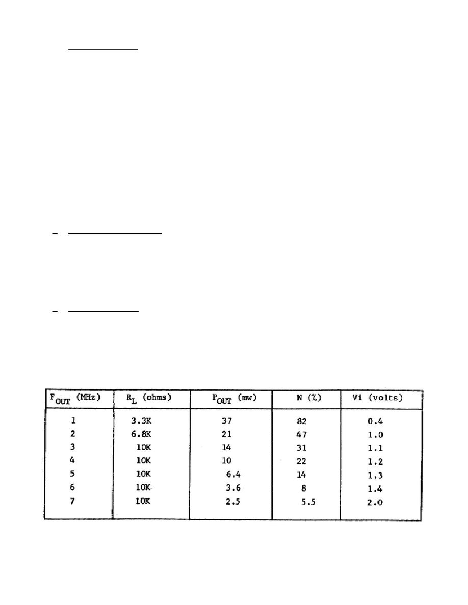
The capabilities of the multiplier circuit are determined
by applying a constant input frequency of 1 MHz from a signal generator, which is
adjusted to produce the optimum drive amplitude for the particular frequency ratio
under test. The load impedance is adjusted by the substitution of various small,
high-frequency-type carbon resistors until the maximum power output is obtained.
The tuned circuit LC is kept at a medium value of impedance (XL = XC = 300 ohms) so
that a loaded Q of 30 or more can be obtained at the higher harmonics.
In the
chart below FOUT is the output frequency, RL is the
23


 Previous Page
