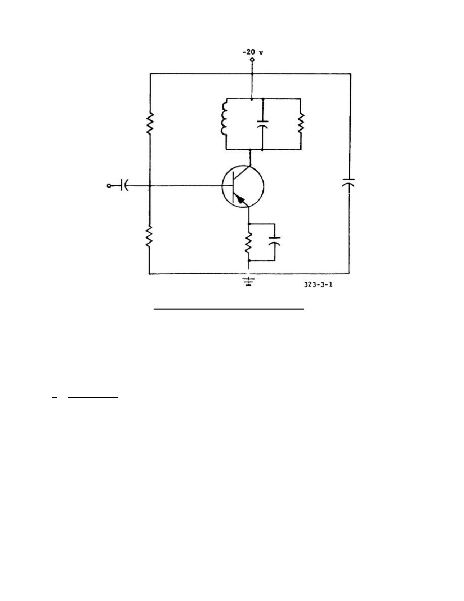
Figure 3-1.
Frequency multiplier.
load impedance, POUT is the power output, N the efficiency, and Vi is the root
means square (rms) input voltage.
The chart shows that if the frequency ratio
(multiplication factor) increases, the power output And efficiency will decrease.
You will also note that the input voltage must be increased for each increase in
frequency ratio so that a usable output can be obtained.
Outputs above the
frequency ratio of 5 to 1 are generally not capable of driving the following stage.
c. Limitations. It will be noted that the efficiencies (N) are reasonably close
to the expected values (N = 100/n) at the second, third, and fourth harmonics, but
become much lower at the higher harmonics. This is probably because of the fact
that the minimum collector current pulse duration that could be obtained was 1/8
microsecond, which corresponds to one-half cycle at an output frequency of 4 MHz.
At higher output frequencies, this input pulse bridges an excessive portion of the
output voltage cycle, and actually extracts energy from the tuned circuit during a
portion of the cycle.
3-3.
DRIVER AND POWER AMPLIFIER STAGES
Amplifier stages designed primarily to raise the power level of the signal are
known as driver and power amplifiers. Driver stages usually develop power
24


 Previous Page
