2-3.
MILLER-EFFECT MODULATOR
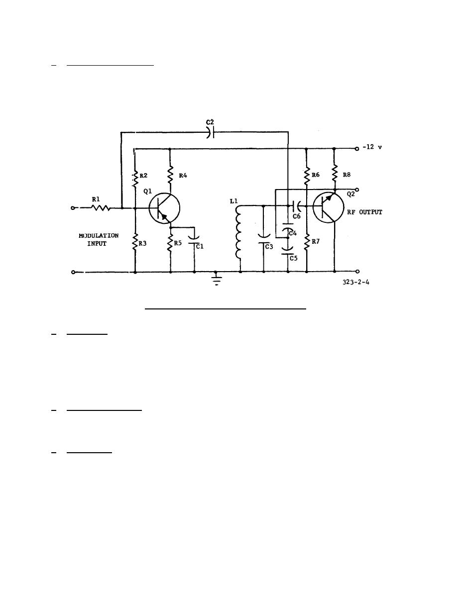
The modulator shown in figure 2-4 employs the Miller
effect to vary the equivalent capacitance across a tuned circuit. In the circuit
diagram, a complete modulator-oscillator is shown.
Transistor Q2 operates as a
Feedback is from the emitter through a capacitively tapped
tuned circuit to the base. The operating point is determined by the conventional
base voltage divider R6, R7, and emitter bias resistor R8.
Figure 2-4.
Miller-effect modulator.
b. Operation.
The modulator, Q1 has an input capacitance at the base that is
approximately equal to the emitter junction capacitance plus the voltage gain
multiplied by the collector capacitance. If the gain is varied by modulating the
operating point of the transistor, the input capacitance of Q1 will change (Miller
effect) and frequency modulation occurs.
2-4.
REACTANCE MODULATOR ASSEMBLY
a. Speech Amplifier.
The transmitter speech amplifier shown in figure 2-5
amplifies the audio-frequency signals from an external microphone or a remote
source.
The amplified output from this emitter follower is coupled through
coupling capacitor C1 and isolating resistor R3 to the oscillator circuit.
b. Oscillator.
The output from the speech amplifier modulates the modified
Colpitts oscillator to provide an FM output.
12


 Previous Page
