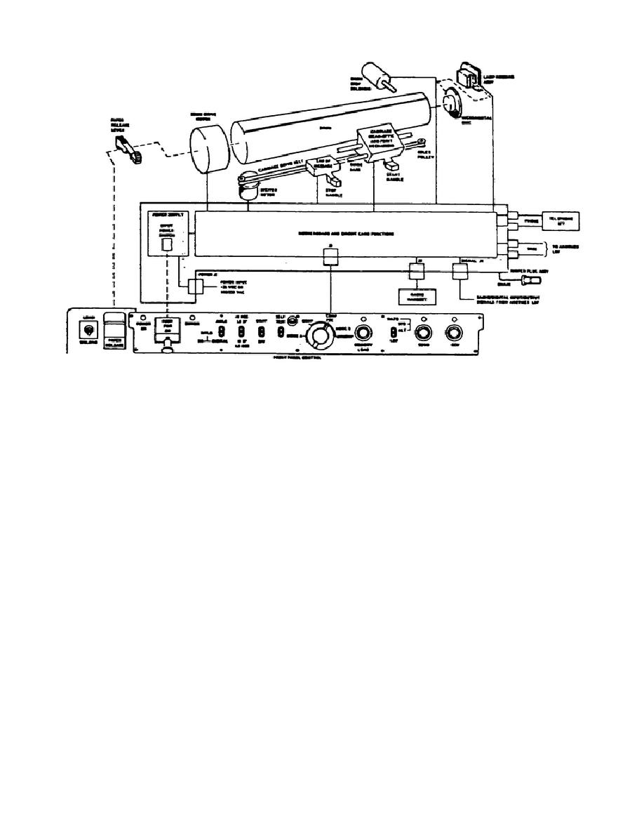
Figure 5. Simplified system functional diagram.
c. Carriage frame assembly. The carriage frame assembly contains the end-of-message
assembly, carriage assembly, and guide bars; and also contains the stepper motor and drive belt which
facilitate the carriage assembly movement during scanning and printing operations. The speed of the
stepper motor and the carriage assembly is controlled by the HI RES LO SP/HI SP LO RES switch. HI
RES LO SP produces about 96 horizontal lines per inch and HI SP LO RES produces about 64 lines per
inch.
d. Carriage assembly. The carriage assembly (Figure 5) is driven from right to left during the
scanning and printing operations. The carriage is moved by the drive belt which is driven by the stepper
motor. The operator may move the carriage along the guide bars by squeezing the carriage START
handle, which releases the carriage from the drive belt, and manually sliding the carriage with the
START handle. On the carriage is mounted the scan-optic assembly which is used during sending
operations, and the print mechanism which is used during receiving operations. The carriage also
contains a margin lamp which allows the operator to set the start position of the carriage relevant to the
size and content of the copy being sent.
11


 Previous Page
