MM0704, Lesson 1
A recent development in television is the use of high Q series resonant circuit for developing voltages of the order of 70
kV for high intensity, projection-type tubes.
Most resonant radio frequency circuits are made with a variable element so that the frequency of resonance may be
adjusted. A radio receiver, for example, contains several adjustable resonant circuits. Probably the most common
means of adjustment is the variable capacitor. Since the development of the powdered iron core, variation of
inductance has also become simple and popular. At high frequencies, such coils are sometimes resonated with their
distributed capacitance and that of the associated wiring. Using the equation for the frequency of resonance,
you can see that decreasing L, C, or both, results in an increased resonant frequency.
Parallel
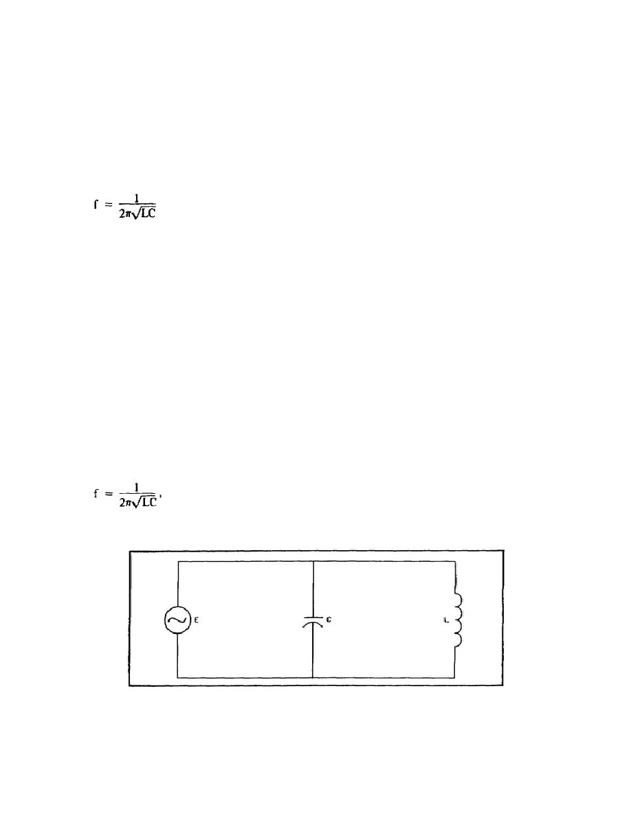
The simplest parallel resonant circuit is inductance and capacitance in parallel, connected to a generator as shown in
figure 1-7. For simplicity, assume that there is no resistance in L or C. The frequency is such that XL = XC. The
currents through the two branches are then equal.
IL = IC, or IL - IC = 0
or vectorially,
jIL - jIC = 0.
Adding these currents to find the total current shows their vector sum to be zero. Since no current is drawn from the
generator, this theoretically perfect resonant circuit has infinite impedance. This is directly opposite to the condition of
series resonance. The requirement that XL = XC is, of course, the same as that of the series resonant circuit. Because
of this, the equation for frequency of resonance,
is the same for both series and parallel circuits.
Figure 1-7. Parallel Resonant Circuit.
13


 Previous Page
