
MM0704, Lesson 4
You can see, then, that a transformer is of little value if you apply pure DC to the primary, since there will be no
sustained voltage induced in the secondary. However, if you were to apply pulsating DC or AC, the magnetic field
would be constantly building up and collapsing, thus continually inducing a voltage in the secondary.
This method of energy transfer, from one circuit to another, is called mutual induction. As a transformer, the single
loop of wire in figure 4-1 is a poor device for the transfer of power. The magnetic field about a straight wire is
relatively weak, and the secondary offers only a short length of wire in which to have a voltage induced. You can, of
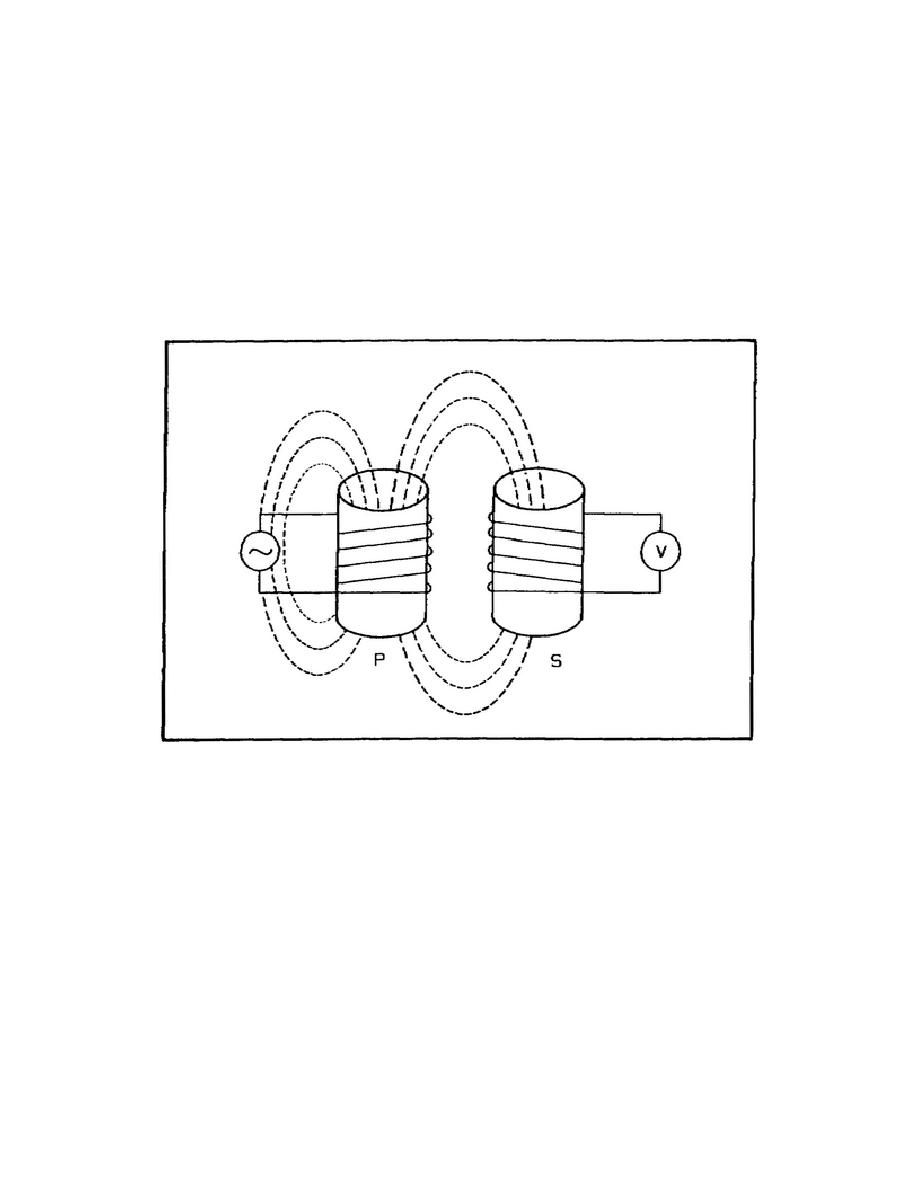
course, increase the strength of the magnetic field by winding the primary in the form of a coil. Thus, if the primary
and the secondary were wound as coils, the induced voltage would be greatly increased. Even with this refinement, the
transformer is still not operating at maximum efficiency. You can see from figure 4-2 that all of the flux building up
from the primary does not cut the secondary. This is called flux leakage. It reduces the efficiency of the transformer.
Figure 4-2. Multiloop Transformer
To help reduce flux leakage, a suitable core material can be inserted between the coils. It provides a path of low
reluctance (resistance) to the magnetic lines of force. In figure 4-3, the primary has been wound on one leg of an iron
core and the secondary has been wound on the other leg. A transformer wound in this manner would still operate at a
low efficiency. It is presented here to show how a transformer works.
Transformer Ratios
Voltage and Turns Ratio. An ideal transformer is one that is 100-percent efficient. This means that in each turn of
the secondary coil, the flux must set up a back EMF of the same value as each turn of the primary coil. The
79

 Previous Page
