MM0704, Lesson 4
From this equation, it is evident that the impedance seen at the primary is equal to the load impedance multiplied by the
square of the ratio of number of turns in primary to number of turns in secondary.
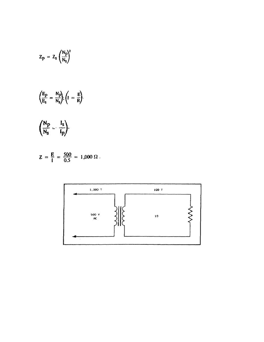
Assume the circuit in figure 4-5 to help clarify the equations above. Figure 4-5 shows a step-down transformer to
which 500 V is applied and which has a 10- resistor as a load on the secondary. There is a potential of 50 V at the
secondary, and 5 amps of current flow in the circuit.
There will also be 0.5 amps of current in the primary
The impedance in the primary is
(Note that the ratio of Zp to Zs is 100 to 1). The impedance ratio of the primary to the secondary is equal to the square
of the turns ratio. This fact is used for impedance matching in amplifiers.
Figure 4-5. Step-Down Transformer.
It is inconvenient to designate a transformer in reference to the turns on each winding by the actual number of turns.
The American Society of Electrical Engineers has established a uniform system of transformer designation in this
respect. The turns ratio of a transformer is the ratio of the number of turns in the primary winding to the number of
turns in the secondary winding. The voltage ratio is expressed as the ratio of the primary voltage to the secondary
voltage. Figure 4-6 shows examples of these two ratios.
Occasionally, a transformer is referred to in terms of its current ratio. This is expressed as the ratio of the current in
the primary to that in the secondary. Figure 4-6 gives a few examples of this ratio also.
83


 Previous Page
