MM0704, Lesson 4
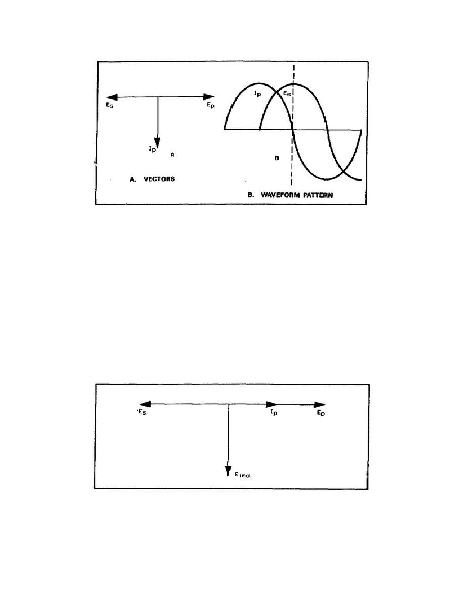
Figure 4-7. Phase Relationship Across a Transformer
Since the induced voltage is dependent upon the rate of change of flux, the rate of change is maximum when the
primary current is passing through zero (figure 4-7B). This would indicate that, at that moment, the induced voltage
would be maximum. The voltage induced in the secondary then lags Ip by 90. The completed vector diagram shows
that there is a 180 phase shift between the primary and secondary voltages. The vectors in figure 4-8 show the
operation of a transformer with a resistive loaded secondary. In this case, the generator works into a resistive load.
The current flowing in the secondary tends to magnetize the iron core in a direction opposite to the magnetizing action
of the primary circuit. This causes a lower EMF in the primary. This decreases the opposition to current flow in the
primary so that it approaches that of pure resistance. Therefore, Ep and Ip are practically in phase. Previously, you
found that the induced voltage lags the primary current by 90. If you picture the secondary winding as a generator, the
voltage induced will be the source of voltage pressure that causes current to flow in the secondary. Therefore, consider
the secondary circuit as a series resistive-inductive (RL) circuit. In actual transformers, the inductance values are quite
large in comparison to the resistive loads, so you can say that the secondary current lags the induced voltage by
approximately 90. If you take the voltage from the secondary across the resistor, the current (Is) and the voltage (Es)
are in phase. Ep and Es are 180 out of phase.
Figure 4-8. Vectors and Phase Relationship with Secondary Loaded
85


 Previous Page
