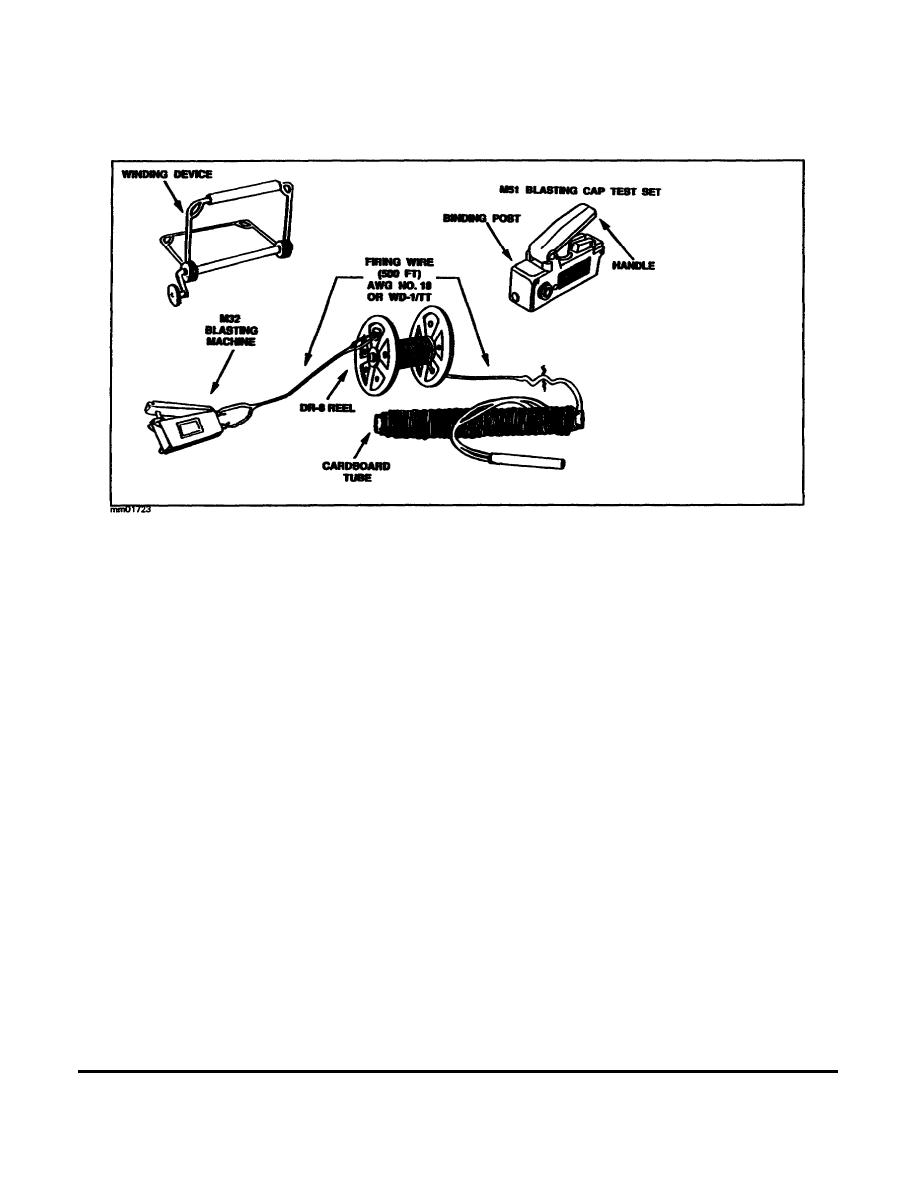
system must not be used during electrical storms, sandstorms, or snowstorms. An electric firing system consists
of testing equipment, a blasting machine, firing cable, and an electric blasting cap, as shown in Figure 1-19.
Figure 1-19. Electric firing system.
Testing Equipment. There are two types of electrical continuity testers used in electric firing systems.
These testers are used to test current flow, both in firing lines and in electric blasting caps, before tying in to the
explosive charge.
The most common tester is a galvanometer, shown in Figure 1-20. It uses a self-contained battery to determine
continuity. You must ensure that the correct battery is used. Two types of battery are authorized for use. One is
used in temperatures above 0F, and the other is used in temperatures below 0F. The use of an unauthorized
battery may result in the accidental detonation of blasting caps during testing. Procedures for testing the
galvanometer and the firing line are as follows.
Check the galvanometer by holding a piece of conductive metal across its terminals. If the battery is good,
the needle will show a wide deflection.
Separate the firing wire conductors at both ends. Touch those at one end to the galvanometer posts. The
needle should not move. If it moves, the firing wire has a short circuit.
Twist the wires together at one end. Touch those at the other end to the galvanometer posts. This should
cause a wide deflection of the needle. No movement of the needle indicates a break in the wire. A slight
movement indicates a high resistance, which may be caused by a dirty wire, loose wire connections, or wire
with several strands broken.
Twist the free ends of the firing wire together after testing.
The other tester is the M51 blasting cap test set. This test set was developed to replace the blasting galvanometer
for testing firing line continuity. It is a self-contained unit, with a magneto-type generator and an indicator
MM0170
1-28


 Previous Page
