the RF stages, hence, larger valued components are needed in the IF stages.
The
last IF stage is generally followed by a limiter stage.
This limiter is
essentially another IF amplifier arranged so that it limits both positive and
negative outputs.
3-2.
TRANSISTORIZED IF AMPLIFIER
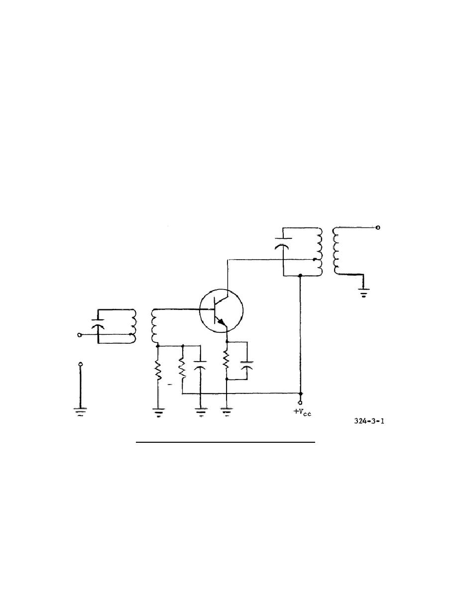
A typical circuit for a transistorized IF amplifier is shown in figure 3-1. The
circuit's collector current is determined by a voltage divider on the base and a
large resistance in the emitter lead. The input and output signals are coupled by
means of tuned transformers. The collector of the transistor is connected to a tap
on the output transformer to provide proper matching for the transistor and also to
make performance of the stage relatively independent of variations between
transistors of the same type. The gain of a transistorized IF amplifier decreases
if the emitter current decreases. This current property of the transistor can be
used to control the gain of the IF amplifier so that weak signals and strong
signals produce the same output power. Typical circuits for changing the gain of
an IF amplifier in accordance with the strength of the received signal are
explained in lesson 4.
Figure 3-1.
Transistorized IF amplifier.
3-3.
FOUR-STAGE IF AMPLIFIER
The circuit shown in figure 3-2 uses synchronous, single-tuned transformers for
interstage coupling.
Excellent bias stability is attained by connecting the base
of each transistor to dc ground and using separate supplies for the collectors and
emitters.
28


 Previous Page
