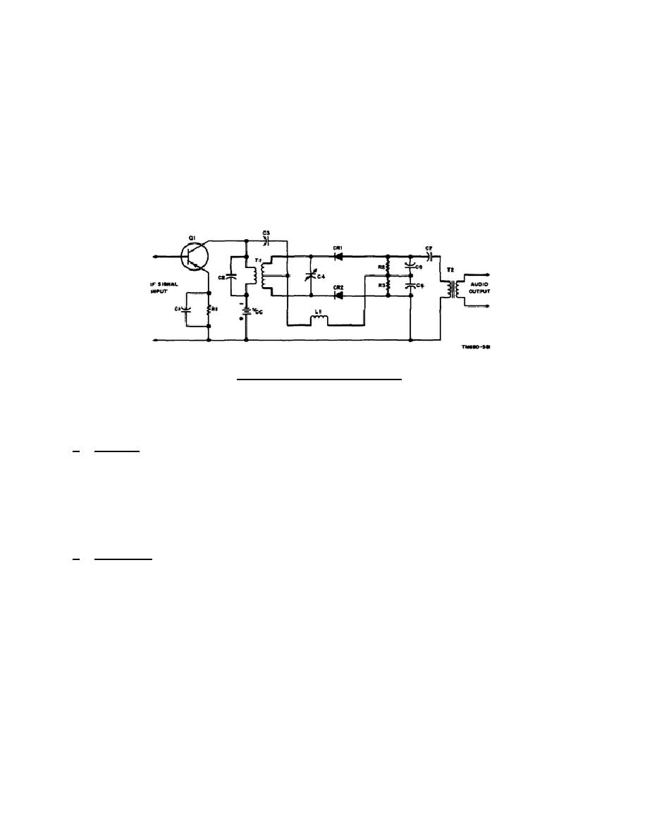
T1 form a parallel resonant circuit for the IF signal that is coupled through the
transformer to the discriminator.
Capacitor C3 couples the IF signal to the
secondary of transformer T1 for phase shift comparison.
The IF signal, coupled
across capacitor C3, is developed across coil L1. Capacitor C4 and the secondary
of transformer T1 form a resonant circuit for the IF signal coupled through the
transformer.
The top half of transformer T1 secondary, diode CR1, coil L1, load
resistor R3, and filter capacitor C5 form one half of the comparison network. The
bottom half of transformer T1 secondary, diode CR2, coil L1, load resistor R3, and
filter capacitor C6 form the second half of the comparison network.
The audio
output of the discriminator circuit is taken from the top of capacitor C5 and the
bottom of capacitor C6.
The audio output is coupled through capacitor C7 to the
primary of transformer T2.
The audio signal, coupled through transformer T2, is
applied to the following stage.
Figure 3-3.
Discriminator.
3-5.
SLOPE DETECTOR
a. Purpose. A slope detector converts the frequency changes of a carrier signal
into amplitude changes. The amplitude changes can then be detected by an AM diode
detector or an AM transistor detector. The input and output waveforms of a slope
detector and an AM diode detector are shown in figure 3-4.
The IF signal with
frequency deviations is applied to slope detector Q1. The output of slope detector
Q1, the IF signal with amplitude and frequency deviations, is applied to diode
detector CR1. The resultant output is an audio signal which is equivalent to the
frequency deviations of the IF input signal.
b. Operation.
The IF signal coupled through transformer T1 is applied to the
base circuit. The resonant circuit, consisting of coil L1 and capacitor C2 (tuned
slightly off the carrier frequency), develops a large amount of IF signal when the
frequency deviation is near the resonant frequency. As the frequency deviation of
the IF signal becomes lower than the resonant frequency of the resonant circuit, a
smaller amount of IF signal is developed. A large amount of IF signal added to the
bias voltage developed across resistor R1 increases the emitter-base bias, and a
small amount of IF signal is developed. A large amount of IF signal added to the
bias voltage developed across resistor R1 increases the emitter-base bias.
The
emitter-base bias is therefore increasing and decreasing as the frequency of the IF
signal increases and decreases, respectively. Since the bias of slope detector Q1
changes at the frequency deviation rate, the gain also changes at the frequency
deviation rate.
Thus, the output of the slope detector is an IF signal that is
changing
30


 Previous Page
