
2-2.
DIRECT-TYPE SYNTHESIZER BLOCK-DIAGRAM ANALYSIS
To illustrate one type of frequency synthesizer for tactical use, we will make a
block-diagram analysis of a direct-type synthesizer.
a. Synthesizer Operation.
The synthesizer module of Radio Set AN/PRC-74 shown
in figure 2-1 consists of assemblies Al through A9.
The combination of these
assemblies provides a series of crystal-controlled oscillators, mixers, bandpass
filters, and amplifiers to generate a selectable output signal in the range of 3.75
to 13.749 MHz.
The selectable output signal frequency is always 1,750 kHz above
the RF signal selected by the radio set for operation. Thus the operating range of
the radio set is 2.0 to 11,999 MHz. The l-kHz step frequency selector switch, S1,
10-kHz step frequency selector switch S2, 100-kHz step frequency switch S3, and MHz
frequency selector switch S4 select a crystal for each of their respective
oscillator circuits. All selector switches and controls necessary for synthesizer
operation are located on the front panel. Since this is a direct type of frequency
synthesizer, all frequencies are generated by crystal oscillators.
b. Crystal Assemblies.
Crystals with their step frequency selecting switches
are located on assemblies Al, A2, A3, and A4.
Assemblies A3 and A4 also contain
the oscillator circuits associated with their crystals.
The two oscillators for
the crystals in assemblies Al and A2 are located on assembly A5.
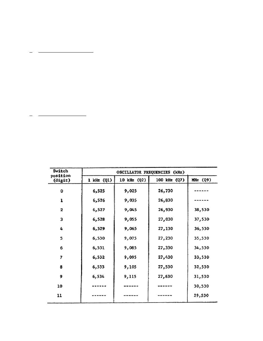
The step
frequency switch positions and corresponding frequencies are shown in table I
below.
The frequency labels on the oscillator controls may give the impression
that the output frequencies are 1, 10, and 100 kHz.
This is not the case; the
frequencies generated by the oscillators appear in increments of those values.
TABLE I
OSCILLATOR FREQUENCIES
327 L2
17

 Previous Page
