required sensitivity and stability. Clockwise rotation of this control will
reduce feedback and increase sensitivity.
(3) A change in the zero position on the indicating galvanometer is
usually caused by an offset in the amplifier. Correction of such a change
should be made with the zero control on the amplifier - not that on the
indicating galvanometer.
If the reverse procedure is used, changes in
either the gain control position or the sensitivity switch on the indicating
galvanometer will result in further changes in the position of the
galvanometer zero.
b. Additional adjustments. The optical system is factory adjusted so
that the light strips will fall on the photo cell mask slits when the
amplifier ZERO control is set to its midposition. After transportation, or
after a heavy overload, it may be found that coincidence can no longer be
obtained by any adjustment of the control. In this event, the cover of the
instrument may be lifted off after removing the four screws along the bottom
edge of the sides of the case. Set the ZERO control to the midposition of
its travel and loosen the three screws holding the disc upon which the
suspension is mounted. The galvanometer suspension and magnet assembly can
then be rotated on its central pivot until the light strips are coincident
with the slits in the photo cell mask.
5.
Theory of operation. The Model 9460A Nanovolt Amplifier is housed in
a metal case provided with a terminal for ground connection. A light source
is mounted on the rear panel and the light is focused onto the mirror of a
highly-sensitive galvanometer suspension.
The suspension is oil-filled to
reduce the effects of mechanical vibration and is mounted between the poles
of a powerful magnet which can be rotated upon its insulator base to provide
coarse zero adjust.
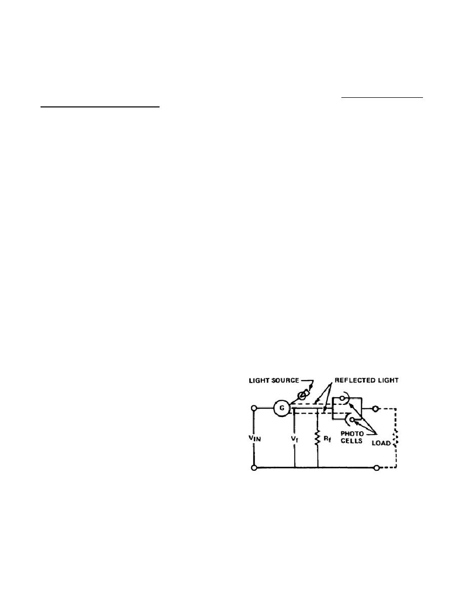
a. The light from the suspension is reflected onto a mirror which is
rotated by a fine zero control on the right side of the front panel. The
light source is masked leaving three adjustable slits. The strips of light
are reflected through the optical system as shown in Figure 2-11 onto two
photo cells. The photo cells are also
masked leaving two slits in front of
each cell. The slits are arranged so
that the light strips illuminate only
half the width of each slit. In this
condition, the output of the two photo
cells is equal.
Any change in
position of the pattern of light
falling on the photo cell mask due to
galvanometer deflection causes a large
increase in the output of one photo
Figure 2-11. Simplified optical
cell and a similarly large decrease in
system
the output of the other photo cell.
b. The two photo cells are connected in parallel opposing and the voltage
appearing across the combination is zero when the cells' output are equal.
When the cell outputs are unbalanced there is a current across the combination
35


 Previous Page
